 Website:
Alpha Moisture Systems Ltd
Group: HALMA
Catalog excerpts

AMT-Ex Dewpoint Transmitter User Manual Alpha Moisture Systems Alpha House 96 City Road Bradford BD8 8ES England Tel: Email: info@amsytems.co.uk Websites: amsystems.co.uk and SADPmini2.com
Open the catalog to page 1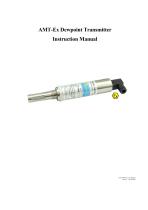
AMT-Ex Dewpoint Transmitter Instruction Manual 1628 AMT-Ex User Manual Issue 9 05/10/2023
Open the catalog to page 2
General Information The Model AMT-Ex Dewpoint Hygrometer is a 3 wire 4-20mA powered transmitter, used for continuous measurement of moisture in a process gas or compressed air. The Model AMT-Ex transmitter can be factory configured to output a 4-20mA linear signal for any of the following moisture units:- ºC or ºF dewpoint, ppm(v), ppb(v), g/m3, and lb/MMSCF. The long lasting sensing element offers excellent sensitivity, repeatability and response speed. Each unit is supplied with a Certificate of Calibration, traceable to International Humidity Standards, validating accuracy to ± 2ºC dew...
Open the catalog to page 4
It is the responsibility of the user to ascertain the suitability of the AMT-Ex for use in hazardous areas. Risk assessments should be performed prior to use, taking into account the AMT-Ex certifications, and the location and the gas being monitored etc. Installing the AMT-Ex in a Air/Gas Sampling System The piping installation schematic diagram (see section 3.1) shows all components, which could be used in a dry gas measurement application although not all the items shown will be required for every installation. Care should be taken to ensure that the sample presented to the AMT-Ex is not...
Open the catalog to page 5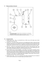
Piping installation Schematic MAIN PROCESS LINE NOTES a. The sample point should be on the upper surface of a horizontal pipe or on a vertical section of pipe, where ever possible. b. The sample tube should run, continually, upwards from the sample point. If this is not possible an inspection port or drain tap should be installed at the lowest point in the system. Component Index 1) Sample Isolation Valve - This is a recommended item as it allows access to the sample system without interrupting the main process line. 2) Sample Tube – This should be stainless steel for dry air or gas...
Open the catalog to page 6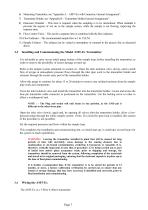
6) Measuring Transmitter, see “Appendix A – AMT-Ex with Connector, General Arrangement”. 7) Transmitter Holder, see “Appendix B – Transmitter Holder General Arrangement”. 8) Desiccant Chamber – This item is required when the sampling is to be intermittent. When installed it prevents the ingress of wet air to the sample system, while the sample is not flowing, improving the response time. 9) Flow Control Valve – This can be a separate item or combined with the flow indicator. 10) Flow Indicator – The recommended sample flow is 2 to 3 SL/M. 11) Sample Exhaust – The exhaust can be vented to...
Open the catalog to page 7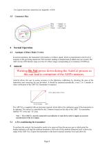
For typical electrical connection see Appendix A & B: Connector Pins = Supply -ve = Supply +ve = mA output Normal Operation Analogue 4-20mA Mode (3-wire) In normal operation, the transmitter will produce a 4-20mA signal, which is proportional to the level of moisture in the gas being monitored. The moisture reading is sampled and up dated once per second. The AMT-Ex has 3020 distinct steps over the 4 to 20mA range corresponding to a resolution of 0.005mA. Warning Do Not power down during the AutoCal process as this can lead to corruption of the AMTs memory. AutoCal allows the user to ensure...
Open the catalog to page 8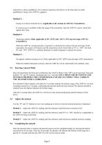
transmitter to attain equilibrium. (For technical questions and advice on the time taken to attain equilibrium Contact your AMT-Ex supplier) Method 1: Expose to a known moisture level. (Applicable to all versions of AMT-Ex Transmitters) If a known gas is available within the range of the transmitter, then the AMT-Ex can be AutoCaled against this value. Method 2: Saturating method. (Only applicable to 0ºC (32ºF) and –20ºC (-4ºF) top end range AMT-Ex transmitters) When the AMT-Ex sensing element is exposed to a dewpoint level above the top end range of the transmitter, the sensor will...
Open the catalog to page 9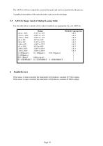
The AMT-Ex will now output the corrected dewpoint and can be reinserted into the process. A graphical description of the autocal modes is given on the next page. AMT-Ex Range AutoCal Method Lookup Table Use the table below to decide which AutoCal methods are appropriate for your AMT-Ex. Faults/Errors If the sensor is short-circuited, the transmitter will produce a constant 20.75mA output. If the sensor is open-circuited, the transmitter will produce
Open the catalog to page 10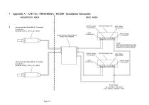
Appendix A – AMT-Ex / PR5104BB2A / DS1200 - Installation Schematics
Open the catalog to page 12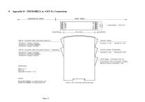
Appendix B – PR5104BB2A to AMT-Ex Connections
Open the catalog to page 13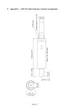
Appendix C - AMT-EX with Connector, General Arrangement
Open the catalog to page 14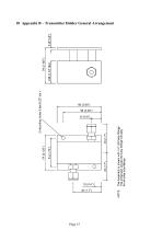
10 Appendix B – Transmitter Holder General Arrangement
Open the catalog to page 15All Alpha Moisture Systems Ltd catalogs and technical brochures
-
Model 6020 User Manual
41 Pages
-
SADPmini2 User Manual
57 Pages
-
AMT User Manual
14 Pages
-
PSS User Manual
17 Pages
-
SADPmini2-Ex User Manual
86 Pages
-
DS1200-Exd-AMT-Ex
3 Pages
-
DS1500-Exd
2 Pages
-
DS4000-Exd-AMT-Ex
3 Pages
-
DSP-FCI Portable Hygrometer
3 Pages
-
Model 6020 Exd
4 Pages
-
Model 6020
3 Pages
-
DS1500
3 Pages
-
SADPmini2 Comparison Chart
1 Pages


