FUTUR

FUTUR
ALMATEC air-operated diaphragm pumps prioritize reliability and safety. Proper usage and adherence to safety guidelines are crucial to prevent damage and ensure safe operation. Personnel involved in installation, start-up, handling, or maintenance must thoroughly read and follow the manual.
The FUTUR series pumps are oscillating positive displacement pumps based on the double diaphragm principle, designed for liquid transport under specified operational parameters. Despite safety measures, potential dangers such as leakages or mechanical damages may occur.
Pumps should be stored in a ventilated, dust-free environment with temperatures between 15°C and 25°C and humidity below 65%. They must be protected from moisture, dirt, UV radiation, and mechanical impacts.
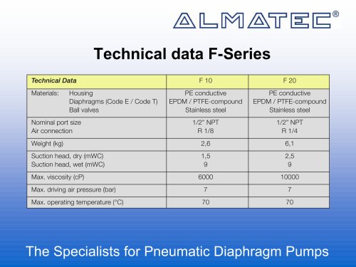
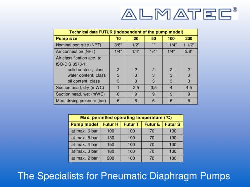
The document provides detailed specifications for various pump sizes, including dimensions, nominal port sizes, air connection requirements, weight, suction head, maximum permissible driving pressure, sound pressure levels, and operating temperature limits.
ALMATEC ensures quality through certification and extensive final control. The FUTUR series is specifically developed for the semiconductor industry, assembled in clean rooms, and tested with de-ionized water. Proper commissioning requires understanding the unique features of these pumps.
Pumps must be installed without tension and should not serve as fixed points for piping. Compensators are recommended for installations with expected movements or vibrations. Shut-off valves should be installed before and after the pump for ease of maintenance.
The connection pipes should match the pump's nominal port size to prevent cavitation and performance loss. The suction line should have an upward gradient to prevent air bubble formation.
The air supply line must match the pump's connection size and meet specific air quality standards. In humid environments, precautions against icing are necessary.
After connecting all lines, the pump is ready for operation. The driving air pressure should be adjusted to meet performance needs without exceeding limits. The pump is self-priming, and pre-filling is unnecessary.
Only qualified staff should handle installation, operation, and maintenance. Regular checks and maintenance are necessary to ensure safety and functionality. Pressure tests should be conducted with caution to avoid damaging the pump.
Optional equipment for diaphragm monitoring is recommended to prevent fluid intrusion into the air side of the pump in case of diaphragm rupture. A non-return valve is advised to protect devices like pulsation dampers or pneumatic valves.
Regular inspection of the muffler is necessary to prevent blockages that could lead to damage. When handling hot liquids, avoid prolonged standstill to prevent leaks and blockages. Ensure compliance with safety advisories and inspect any liquid pools near the pump for potential hazards.
Avoid chemical and biological reactions in the pump chamber and prevent freezing of liquids. Before disassembly, ensure the pump is emptied, rinsed, and disconnected from energy sources. Use appropriate safety equipment when handling aggressive or toxic liquids.
Follow specific steps for disassembling and assembling the pump, ensuring all damaged sealing elements are replaced. Allow time for gaskets to settle after assembly.
Temperature and pressure limitations are based on housing material limits. Note that PE maintains strength at low temperatures, while PTFE remains stable over a wide range. Avoid freezing or crystallization of fluids, as this can affect pump performance.
Common issues include blocked air supply lines, worn piston rings, and diaphragm ruptures. Solutions involve cleaning, replacing parts, and ensuring proper air supply.
A list of spare parts is provided, detailing materials and part numbers for different pump sizes.
The document provides detailed technical specifications, assembly instructions, and special equipment options for the FUTUR series pumps and associated components. It includes information on materials, part numbers, and installation procedures for various components such as diaphragms, O-rings, gaskets, and pulsation dampers.
The document lists numerous components with their respective materials and part numbers. Key materials include PTFE, FKM, PEEK, and UPPE, among others. The components are categorized by their function, such as diaphragms, O-rings, gaskets, and bolts, with specific part numbers for different pump sizes.
Detailed assembly instructions are provided for the pneumatic stroke counting system and diaphragm monitoring sensor. The document outlines the steps for installing these systems, including the removal and connection of specific components. It emphasizes the importance of maintaining a minimum counter pressure for optimal function.
The document highlights the need for using original product connectors, such as Flaretek®-connectors, to ensure proper functioning and sealing of the pumps. It also provides safety hints and operational guidelines for the installation and use of pulsation dampers.
Options for special equipment include pneumatic stroke counting systems (codes C 9 and C 10), diaphragm monitoring sensors (code D), and Flaretek®-connectors for PFA pipes (code G). Each option is described with its components and installation requirements.
The document includes technical data for pulsation dampers, such as dimensions, weight, air connection specifications, and maximum permissible pressures and temperatures. It also provides a spare parts list for various damper sizes, detailing the materials and part numbers for each component.
The document serves as a comprehensive guide for the assembly, installation, and maintenance of FUTUR series pumps and their components. It emphasizes the importance of using specified materials and following detailed procedures to ensure optimal performance and safety.
Catalog excerpts
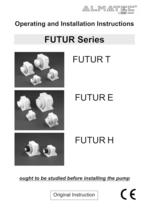
Operating and Installation Instructions FUTUR Series FUTUR H FUTUR E FUTUR T ought to be studied before installing the pump Original Instruction
Open the catalog to page 1
FUTU R · page 3 Introduction ALMATEC air-operated diaphragm pumps are constructed according to the state of the art and they are reliable. Imminent danger by operating error or misuse can lead to damages of properties and/or persons. The pumps are to be applied for the intended use and in a safety-related proper condition only. Each person working on the ALMATEC air-operated diaphragm pumps concerning installation, start-up, handling or maintenance has to read this manual completely and in an attentive way and has to follow all mentioned procedures and safety notes. General description of the...
Open the catalog to page 3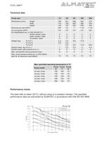
FUTU R · page 4 Technical data Pump size 10 20 50 100 200 Dimensions (mm), length width height 185 114 130 201 150 167 246 200 222 303 260 265 374 330 345 Nominal port size (NPT) 3/8“ 1/2“ 1“ 1 1/4“ 1 1/2” Air connection (NPT) Air classification acc. to ISO-DIS 8573-1: solids content, class water content, class oil content, class 1/4“ 2 3 3 1/4“ 2 3 3 1/4“ 2 3 3 1/4“ 2 3 3 3/8” 2 3 3 Weight (kg), FUTUR T FUTUR H FUTUR E 2,3 2,6 - 4,2 5,0 2,8 8,8 - 5,8 17,6 - 11,8 - - 29,0 Suction head, dry (m.w.c.) Suction head, with product (m.w.c.) 1 8 2.5 9 3.5 9 4 9 4,5 9 Max. permissible driving pressure...
Open the catalog to page 4
FUTU R · page 6 Commissioning The ALMATEC Maschinenbau GmbH is certified as a modern, quality-orientated enterprise according to DIN EN ISO 9001:2008 and 14001:2005. Before release for dispatch, any FUTUR pump has to undergo an extended final control. The performance data registered during this are archived in our records and can be read back at any time. Every individual part mentioned in the following text is identified by a number in square brackets corresponding with its item number in both the spare part list and the exploded view. The series FUTUR has specially been developed to meet the...
Open the catalog to page 6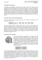
FUTU R · page 7 Installation into the piping UV-radiation can damage the housing parts of pumps made of PE. Pumps must be connected load free without any tension. They cannot serve as a fixed point for the piping. Neglecting this causes leakage and maybe even damages. In case movements or vibrations have to be expected, we recommend the installation of compensators upstream and downstream of the pump. The FUTUR can be used standing free or can be installed using the anchor bolt bushings [27]. The operator is responsible for an adequately stability and an appropriate fixation of the piping according...
Open the catalog to page 7
FUTU R · page 8 Start-up and operation of the pump The pump is ready to be operated after the connection of all lines. The pressure of the driving air should be limited to the amount required to meet the performance needed. Excessive pressure increases both the air consumption and the wear of the pump. However, the air-pressure should not be lower than 1,5 bar to ensure a steady and reliable flow. The pump is regulated by tuning the flow rate of the air (needle valve). An empty pump has to be driven slowly. In general, dry running at high frequency or for an extended period of time has to be...
Open the catalog to page 8
FUTU R · page 9 danger potential, if necessary safety measures are to be taken. „h Chemical and biological reactions in the product chamber of the pump (mixture of different substances) and the freezing of the liquid have to be avoided. „h Before starting to disassemble the pump, take care that the pump has been emptied and rinsed. Both ports piping are to be closed and drained if applicable. Further the pump has to be cut off from any energy on the air and product side. If the pump is being deported from the plant, a reference about the delivered liquid has to be attached. „h Procedure for rinsing:...
Open the catalog to page 9
FUTU R · page 10 Disassembly When dismantling a pump the mentioned procedures and safety notes on the pages 6 - 10 have to be considered generally. On both sides of the pump unscrew the head screws [29,30] with a screwdriver and remove the base frame [25]. Take out O-rings air channel [26]. Screw the muffler [20] (at pump size 10 additionally the adapter muffler [21]) and the black plug [18] out of the side housing left hand [16]. Insert suitable round bar in one of the bore holes of the union nut [22] of the side housing left hand [16] and use it to unscrew the union nut [22]. Remove side housing...
Open the catalog to page 10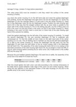
FUTU R · page 11 damage O-rings, moisten O-rings before assembly!). The valve stops [5,6] must be screwed in until they match the surface of the center housing [1] flushly. Lay down the center housing [1] on the left hand side and insert the gasket diaphragm [10] carefully. Screw the diaphragm bolt right hand [13] into the diaphragm [7]. Screw the diaphragm [7] into the cascade sleeve [11] and push it into the center housing [1]. Insert the O-ring diaphragm outer [9] into the diaphragm recess. Position the side housing right hand [14] in that way that the straight surface with the air bore holes...
Open the catalog to page 11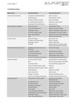
FUTU R · page 12 Troubleshooting Malfunction Possible Reason Solutions/Remarks pump does not operate air supply line blocked/closed muffler blocked working chambers blocked air control system defective discharge line blocked/closed open air supply clean/replace muffler remove blockage replace air valve system clean/open line pump operates unsteadily piston rings worn air control system worn diaphragm rupture air control system soiled check valve blocked icing replace piston rings replace air control system replace diaphragm, clean pump clean/replace air control system cleaning, removal of bulk...
Open the catalog to page 12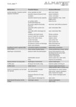
FUTU R · page 13 Malfunction Possible Reason Solutions/Remarks pumps operates, however suction capacity insufficient pump operates too fast operation beyond physical limits cavitation operation beyond pump capacity air cushion within suction/discharge line dry suction against discharge pressure valve filter within suction line closed valve filter within discharge line closed container with liquid empty vacuum inside the container wear of the check valves suction line leaky suction line blocked air pressure cushion at discharge check valve blocked start more slowly adjust installation check, cool...
Open the catalog to page 13All ALMATEC Maschinenbau GmbH catalogs and technical brochures
 CXM Series Brochure A4
6 Pages
 C- Serie
8 Pages
 FUTUR Series
8 Pages
 C-Series Brochure A4
6 Pages
 Chemicor Brochure A4
8 Pages
 Biocor Brochure A4
8 Pages
 AHD/AHS Series Brochure A4
8 Pages
 E-Series AODD Pumps
12 Pages
 Almatec brochure
16 Pages
 F-SERIES
16 Pages
 CX
CX12 Pages
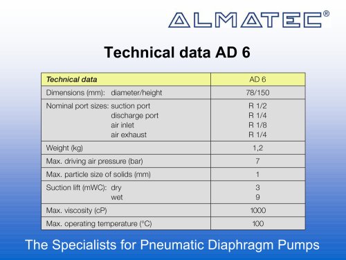
 AD 6
AD 68 Pages
 AH
AH20 Pages
 CHEMICOR
20 Pages
 A-SERIE
28 Pages
 E-SERIES
12 Pages
 Decontamination-Sheet
1 Page


Archived catalogs
 Almatec Market Brochure
8 Pages