CX

CX
ALMATEC air-operated diaphragm pumps are engineered for reliability and safety. Proper usage and adherence to the manual are crucial to prevent damage or injury. All personnel involved in installation, operation, or maintenance must thoroughly read and follow the manual.
The ALMATEC CX series pumps function as double diaphragm pumps, utilizing compressed air to move diaphragms and transport liquids. Adhering to operational parameters and safety guidelines is essential, though residual risks like leaks or mechanical damage may still occur.
Pumps should be stored in a ventilated, dust-free environment with temperatures between 15°C and 25°C and humidity below 65%. Protection from moisture, UV radiation, and mechanical impacts is necessary.
ALMATEC pumps comply with DIN EN ISO 9001:2008 and 14001:2005 standards. Ensure the pump meets EU machinery directives and is suitable for the intended application before operation. Identification details are on the pump's plates.
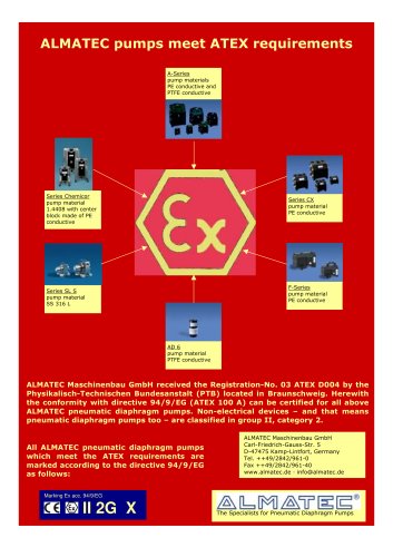
For flammable liquids or explosive environments, use pumps with conductive plastic housings. Grounding is required, and additional safety measures are necessary when using non-conductive diaphragms.
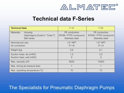
Specifications for models CX 10, CX 20, CX 50, and CX 130 include dimensions, weight, maximum particle size, suction height, operating pressure, temperature, viscosity, and sound levels.
Pumps must be installed load-free to prevent leaks and damage. Proper piping and air supply are crucial. The pump is self-priming and can run dry at low speeds. Excessive air pressure increases wear and should be avoided.
Only qualified personnel should perform installation and maintenance. Regular checks and adherence to torque specifications for housing bolts are necessary. Safety measures include using shut-off valves and ensuring the pump is disconnected from pressure during maintenance.
In case of diaphragm rupture, fluids may enter the air side, necessitating protective measures for air supply lines. Regular inspection of the muffler and flushing of the pump are recommended to prevent blockages and ensure safety.
1. Use appropriate safety equipment as per the safety data sheet during maintenance and operation.
2. Check the pump's tightness before operation and use proper lifting gear for heavy modules.
3. Replace wear parts like diaphragms during preventive maintenance.
4. Use only original ALMATEC spare parts to maintain warranty.
5. Ensure sufficient ventilation when using nitrogen as a driving gas in closed rooms.
6. Electrical connections should be handled by qualified personnel.
7. Prevent explosive atmospheres by using recommended safety equipment.
8. Include a filled decontamination sheet for pump returns as per 14001-certification requirements.
1. Ensure waste air is deducted above the fluid level when using the pump as a submersible.
2. The pump must be upright for proper function, and all external parts must be resistant to the fluid.
3. Disconnect the pump from system pressure during standstill.
1. Temperature and pressure limits are based on housing material; fluid properties can reduce safe operating temperatures.
2. Below 0°C, elastomers may wear faster, and freezing of the fluid must be avoided.
3. Viscosity and specific gravity changes with temperature can affect flow rate and pump priming ability.
4. Monitor housing bolt tension with temperature variations.
1. Use the provided plastic tool for air control system mounting; no special tools are needed.
2. Follow specific steps for disassembling and reassembling diaphragms and air control systems.
3. Ensure all sealing surfaces are clean and undamaged to prevent leaks.
1. Common issues include blocked air supply, worn piston rings, diaphragm rupture, and insufficient air pressure.
2. Solutions involve cleaning, replacing parts, and ensuring proper air supply and pressure.
3. Address specific malfunctions like insufficient suction capacity and leaking between housing parts with targeted actions.
1. Detailed list of spare parts for different pump sizes (CX 10, CX 20, CX 50, CX 130) with part numbers and materials.
2. Ensure to state the pump's serial number when ordering parts.
1. Visual diagrams of pump models CX 10/20 and CX 50/130 for reference.
Catalog excerpts
ALMATEC Series CX CX 10 – CX 130 Operating and Installation Instructions ought to be studied before installing the pump Original Instruction Introduction ALMATEC air-operated diaphragm pumps are constructed according to the state of the art and they are reliable. Imminent danger by operating error or misuse can lead to damages of properties and/or persons. The pumps are to be applied for the intended use and in a safety-related proper condition only. Each person working on the ALMATEC air-operated diaphragm pumps concerning installation, start-up, handling or maintenance has to read this manual completely and in an attentive way and has to follow all mentioned procedures and safety notes. General description of the machine, appropriate use and residual dangers The ALMATEC CX pumps are oscillating positive displacement pumps and are based on the functional principle of double diaphragm pumps. The basic configuration consists of two external side housings with a center housing between them. Each of the side housings contains a product chamber which is sealed against the center housing by a diaphragm. The two diaphragms are interconnected by a piston rod. Directed by an air control system, the diaphragms are alternately loaded with compressed air so that they move back and forth. In the first figure, the compressed air has forced the left-hand diaphragm towards the product chamber and displaced the liquid from that chamber through the open valve at the top to the discharge port. Liquid is simultaneously drawn in by the right-hand diaphragm, thus refilling the second product chamber. When the end of the stroke is reached, it reverses automatically and the cycle is repeated in the opposite direction. In the second figure, liquid is drawn in by the left-hand diaphragm and displaced by the right-hand diaphragm. The appropriate use of an Almatec air-operated diaphragm pump refers to the liquid transport taking into account the operation parameter mentioned in this manual and in compliance of the given terms for commissioning, operation, assembly, disassembly and maintenance. Even if all necessary safety measures described in this manual have been met, a residual danger exists by leakages or mechanical damages. At sealing areas or connections liquid can be released uncontrollably then. Storage In general the ALMATEC pump is delivered operational and packaged. If the unit is not installed right away, proper storage conditions are important for a trouble free operation later. The pump has to be protected from wetness, coldness, dirtying, UV-radiation and mechanical influences. The following storage conditions are recommended: - Steady ventilated, dust and vibration free storage room - Ambient temperature between 15°C and 25°C with a relative humidity below 65% - Prevention of direct thermal influences (sun, heating) 1
Open the catalog to page 1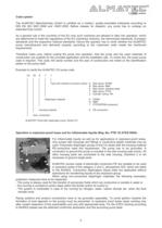
Code system The ALMATEC Maschinenbau GmbH is certified as a modern, quality-orientated enterprise according to DIN EN ISO 9001:2008 and 14001:2005. Before release for dispatch, any pump has to undergo an extended final control. As a general rule in the countries of the EU only such machines are allowed to take into operation, which are determined to meet the regulations of the EU machinery directive, the harmonized standards, European standards and the respective national standards. Hence the operator has to verify whether the ALMATEC pump manufactured and delivered properly according to the...
Open the catalog to page 2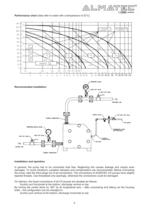
Performance chart (data refer to water with a temperature of 20°C) 35 40 45 50 60 70 80 90 100 120 Recommended installation Installation and operation In general, the pump has to be connected load free. Neglecting this causes leakage and maybe even damages. To avoid vibrations, pulsation dampers and compensators are recommended. Before connecting the pump, take the blind plugs out of all connections. The connections of ALMATEC CX-pumps have slightly tapered threads. Use threadseal only sparingly, otherwise the connections could be damaged. On delivery, the liquid connections of all CX-pumps are...
Open the catalog to page 4
The operator is responsible for an adequately stability and an appropriate fixation of the piping according to the state of the art. To facilitate the installation and maintenance shut off valves should be installed right before and after the pump.The nominal width of the connection pipes has to be chosen in accordance to the connections of the pump. A smaller piping can cause cavitation (suction line) as well as a loss of performance (suction and discharge line). In case the pipe is too big, the dry suction capacity of the pump can decrease. Seal the suction line diligently; hosepipes should...
Open the catalog to page 5
„h Pump must not be operated with a positive suction pressure. „h Depending on the conditions of operation, the liquid conveyed might escape from the pump through the muffler in case of a diaphragm rupture (in this case muffler has to be replaced). For further safety requirements the optional equipment diaphragm monitoring and barrier chamber system are recommended. „h In case of a diaphragm rupture, it might be possible fort he fluid pumped to intrude into the air side of the pump. In very adverse conditions - e.g. pressure within the fluid system during stopped air supply - the fluid might...
Open the catalog to page 6
within the system during standstill. When choosing the pump type, it must be taken into consideration that all external parts - even those non-wetted during standard operation - like covers, shock absorbers, connections etc. must be resistant to the fluid pumped. Please consider as well that depending on the material, the pump must be weight down resp. fixed. Additional temperature hints The temperature and pressure limitations listed on page 3 are solely based on mechanical temperature limits of the housing material used. Depending on the fluid pumped, the maximum safe operating temperature...
Open the catalog to page 7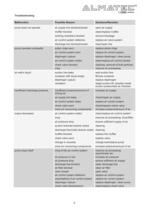
Troubleshooting Malfunction Possible Reason Solutions/Remarks pump does not operate air supply line blocked/closed muffler blocked working chambers blocked air control system defective discharge line blocked/closed open air supply clean/replace muffler remove blockage replace air valve system clean/open line pump operates unsteadily piston rings worn air control system worn diaphragm rupture air control system soiled check valve blocked icing replace piston rings replace air control system replace diaphragm, clean pump clean/replace air control system cleaning, removal of bulk particles improve...
Open the catalog to page 8All ALMATEC Maschinenbau GmbH catalogs and technical brochures
 CXM Series Brochure A4
6 Pages
 C- Serie
8 Pages
 FUTUR Series
8 Pages
 C-Series Brochure A4
6 Pages
 Chemicor Brochure A4
8 Pages
 Biocor Brochure A4
8 Pages
 AHD/AHS Series Brochure A4
8 Pages
 E-Series AODD Pumps
12 Pages
 Almatec brochure
16 Pages
 F-SERIES
16 Pages
 AD 6
AD 68 Pages
 AH
AH20 Pages
 FUTUR
FUTUR20 Pages
 CHEMICOR
20 Pages
 A-SERIE
28 Pages
 E-SERIES
12 Pages
 Decontamination-Sheet
1 Page


Archived catalogs
 Almatec Market Brochure
8 Pages