Catalog excerpts

Operating and Installation Instructions AH Series AH 15 - AH 40 High-Pressure Diaphragm Pumps made of Plastic ought to be studied before installing the pump Original Instruction
Open the catalog to page 1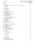
Serie s AH · page 2 CONTENTS page 1. Introduction 3 1.1. General description of the machine, appropriate use and residual dangers 3 1.2. Storage 3 1.3. Codesystem 3 2. Technical data 4 2.1. Performance charts 5 2.2. Dimensions 6 3. Installing the pump 6 3.1. Installation into the piping system 6 3.1.1. Product ports 6 3.1.2. Connecting the air supply 7 3.2. Start-up and operation of the pump 7 3.3. Further safety hints 8 3.4. Additional temperature hints 9 3.5. Providing spare parts 9 4. Disassembly of the elements of construction 10 4.1. Side housings and manifolds 10 4.2. Suction and...
Open the catalog to page 2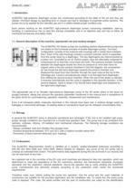
Serie s AH · page 3 1. Introduction ALMATEC high-pressure diaphragm pumps are constructed according to the state of the art and they are reliable. Imminent danger by operating error or misuse can lead to damages of properties and/or persons. The pumps are to be applied for the intended use and in a safety-related proper condition only. Each person working on the ALMATEC high-pressure diaphragm pumps concerning installation, start-up, handling or maintenance has to read this manual completely and in an attentive way and has to follow all mentioned procedures and safety notes. 1.1. General...
Open the catalog to page 3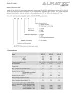
Serie s AH · page 4 plates on the pump itself. Based on the ALMATEC pneumatic diaphragm pump range, ALMATEC high pressure pumps AH 15, AH 25, AH 40 have especially been developed for the requirements of feeding filter presses. Due to the integrated pressure transmission, they can achieve a discharge pressure of 15 bar with an air pressure of 7 bar. Here is an example to illustrate the system of the ALMATEC pump codes: AH 25 E T T - C Optional equipments: C Stroke counting D Diaphragm monitoring Material of E EPDM ball valves: N NBR T PTFE Material of diaphragms: E EPDM N NBR T PTFE-EPDM...
Open the catalog to page 4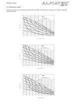
Serie s AH · page 5 2.1. Performance charts Performance data are in accordance with DIN EN ISO 9906. The data refer to water (20°C), without using of a pulsation damper.
Open the catalog to page 5
Serie s AH · page 6 2.2. Dimensions (in mm) A B C D E F G H I K L M N O P Q R S T AH 15 282 152 300 235 112 DN 15 24 1/4” BSP 263 37 276 53 21 6 150 20 10 40 M 8 AH 25 382 200 380 335 160 DN 25 36 1/2” BSP 336 44 376 56 48 8 190 20 12 40 M 8 AH 40 490 270 514 433 220 DN 40 47 1/2” BSP 454 60 484 70 18 8 257 20 12 50 M 10 3. Installing the pump The number in brackets, which is added to every part mentioned in the following explanations, refers to its position in the spare part list and the exploded view. UV-radiation can damage the housing parts of pumps made of PE. The operator is...
Open the catalog to page 6
Serie s AH · page 7 of air locks in the line which would affect the suction lift. If pressurised air chambers are positioned beyond the pump discharge, these have to be disconnected from the pump by non-return valves. As the ALMATEC high pressure pumps regulates itself automatically according to the pressure of the filter press, additionally influencing the pump by a pressurised regulated air chamber cannot be permitted on principle. 3.1.2. Connecting the air supply The air inlet [18] is located in the middle of the center blocks [16]. To supply the pump with driving air sufficiently, an...
Open the catalog to page 7
Serie s AH · page 8 temperature varying between extremes or high temperature difference between the liquid and the surrounding, the housing bolts should be controlled more frequently (interval proposals are available on request). Once the pump is leaking because of insufficient tension of the bolts, it cannot be sealed completely by just tightening the bolts without cleaning the surfaces. The pump has to be opened and the sealing surfaces have to be cleaned carefully. Especially the round sealing groove in the side housing [1] needs to be cleaned diligently. Size AH 15 AH 25 AH 40 Torque...
Open the catalog to page 8
Serie s AH · page 9 „h In case of delivery of hot liquids the wetted pump must not standstill for a longer time, because it could lead to temporary leaks in the valve area and to a blockade of the air control system. „h The relevant effective security advises have to be respected. „h Pools of liquid which appear in the near outer area of the pump have to be inspected on danger potential, if necessary safety measures are to be taken. „h Chemical and biological reactions in the product chamber of the pump (mixture of different substances) and the freezing of the liquid have to be avoided. „h...
Open the catalog to page 9
Serie s AH · page 10 4. Disassembly of the elements of construction When dismantling a pump the mentioned procedures and safety notes on the pages 6-9 have to be considered generally. The general design of the ALMATEC high pressure pumps is simple. Every pump comes along with a mounting tool for the air-valve system [22]. Further special tools are not required. Take out the muffler [20] installed onto the center block [16] before dismantling the pump to protect it against damages during the disassembly. 4.1. Side housings and manifolds After taking the plugs out of the side housings [1] the...
Open the catalog to page 10
Serie s AH · page 11 4.3. Diaphragms After following the instructions above you will now have a unit consisting of the left side housing [1] the center block [16] and the dual stage housing [12] with the housing bolts [10] partly torn out to the left. To disassemble the diaphragms [14] reach behind the right diaphragm [14] and screw it off the shaft [29]. Take out the diaphragm disc [38] afterwards. Insert two long suitable screws (e.g. two housing bolts) into the threaded bores of the supporting disc [21] for approximately 10 mm. Position a round bar as a handle in between them and loosen...
Open the catalog to page 11
Serie s AH · page 12 4.5.3. Air filter To take out the air filter [19] the air inlet [18] has to be screwed off first, afterwards the filter [19] can be unscrewed easily with a big screw driver. 5. Assembly of the elements of construction 5.1. Center block 5.1.1. Air control system PERSWING P® To install the air control system PERSWING P®, first screw in one end cap flushly into the center block [16]. Insert one of the six O-rings, air-valve housing [24] into the end cap from the inside. Moisten the four O-rings [24] of the air-valve housing with a bit of water and push the housing into the...
Open the catalog to page 12All ALMATEC Maschinenbau GmbH catalogs and technical brochures
-
C- Serie
8 Pages
-
FUTUR Series
8 Pages
-
CXM Series Brochure A4
6 Pages
-
C-Series Brochure A4
6 Pages
-
Chemicor Brochure A4
8 Pages
-
Biocor Brochure A4
8 Pages
-
AHD/AHS Series Brochure A4
8 Pages
-
E-Series AODD Pumps
12 Pages
-
Almatec brochure
16 Pages
-
F-SERIES
16 Pages
-
CX
12 Pages
-
AD 6
8 Pages
-
FUTUR
20 Pages
-
CHEMICOR
20 Pages
-
A-SERIE
28 Pages
-
E-SERIES
12 Pages
-
Pumps for low to medium duty
1 Pages
-
Decontamination-Sheet
1 Pages
Archived catalogs
-
Almatec Market Brochure
8 Pages


