

A-SERIE

A-SERIE
ALMATEC air-operated diaphragm pumps are designed with advanced technology for reliability. Proper use is essential to prevent damage, and users must thoroughly read and follow the manual.
The A-Series pumps are oscillating positive displacement pumps using the double diaphragm principle, suitable for liquid transport under specified conditions. Despite safety measures, potential risks like leaks exist.
Pumps should be stored in a ventilated, dust-free environment with temperatures between 15°C and 25°C and humidity below 65%, protected from moisture, dirt, UV radiation, and mechanical impacts.
ALMATEC is certified under DIN EN ISO 9001:2008 and 14001:2005. Pumps must comply with EU machinery directives and standards, with the pump code, serial number, and construction year verifying suitability for applications.
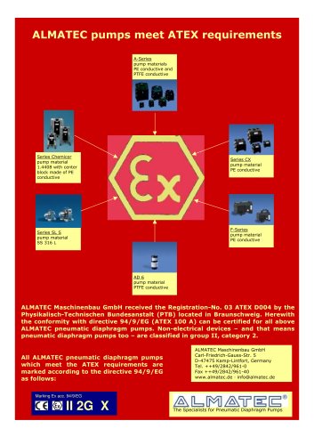
For flammable liquids or explosive environments, pumps with conductive plastic materials are required, and grounding is necessary. Additional safety measures are needed for non-conductive diaphragms.
Technical specifications for models A 08 to A 50 include dimensions, weight, maximum particle size, suction lift, operating pressure, temperature limits, displacement volume, and sound pressure levels.
Performance data are based on water at 20°C without a pulsation damper, following DIN EN ISO 9906 standards.
Proper installation requires attention to UV protection, load-free connections, and appropriate piping to prevent cavitation and performance loss.
Ensure the air supply is free of solids and matches the air inlet size. The PERSWING P® air control system requires oil-free, dry, and clean compressed air. In humid conditions, additional measures like air dryers may be necessary.
Regular checks of torque values for bolts are recommended to maintain pump integrity.
Operational guidelines emphasize maintaining driving air temperature below 50°C and regulating air pressure to meet performance needs without excess. The pump is self-priming when dry and can operate briefly against a closed discharge line.
Regular maintenance includes checking housing bolts and ensuring the pump is turned off during maintenance. The document warns against operating with positive suction pressure and recommends using a non-return valve to protect the air supply line.
Only qualified staff should handle installation, operation, and maintenance. Maintenance requires the complete installation to be turned off, and pressure tests should be conducted with the pump disconnected.
When using the pump as a submersible, ensure waste air is vented above the fluid level and the pump is positioned vertically.
Temperature and pressure limitations are based on the mechanical limits of housing materials. Accelerated wear at temperatures below 0°C is noted, and freezing or crystallization of the fluid should be avoided.
Spare part kits are recommended to be kept in stock. The disassembly process involves careful handling of components to avoid damage.
Reassembly follows the reverse order of disassembly, with proper alignment and cleanliness of components crucial to prevent leaks.
A comprehensive troubleshooting section lists common malfunctions, possible reasons, and solutions.
The document includes detailed spare parts lists for various pump models, specifying materials and part numbers.
Ensure proper assembly, regularly check air supply and control systems, use appropriate spare parts, and monitor for signs of wear.
This document provides detailed technical specifications and assembly instructions for ALMATEC pneumatic double diaphragm pumps and pulsation dampers.
The document lists various components of the pump, including material type and part numbers for different pump sizes.
Instructions for assembling and disassembling the pumps and dampers are provided, emphasizing the importance of tightening housing bolts according to specified torque values.
Materials used in construction must be resistant to the chemicals being pumped, and regular maintenance checks are recommended.
Ensure the pump and damper are emptied and rinsed before disassembly, and special precautions are advised when handling aggressive liquids.
The document includes exploded views of pump sizes and pulsation dampers, as well as a spare parts list for the T-Series dampers.
Catalog excerpts
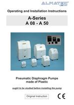
Operating and Installation Instructions A-Series A 08 - A 50 Pneumatic Diaphragm Pumps made of Plastic ought to be studied before installing the pump Original Instruction
Open the catalog to page 1
3 Introduction ALMATEC air-operated diaphragm pumps are constructed according to the state of the art and they are reliable. Imminent danger by operating error or misuse can lead to damages of properties and/or persons. The pumps are to be applied for the intended use and in a safety-related proper condition only. Each person working on the ALMATEC air-operated diaphragm pumps concerning installation, start-up, handling or maintenance has to read this manual completely and in an attentive way and has to follow all mentioned procedures and safety notes. General description of the machine, appropriate...
Open the catalog to page 3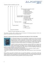
4 Example to clarify the ALMATEC pump code: A 15 T T T - B Optional equipment (separate manual): B Barrier chamber C Stroke counting D Diaphragm monitoring F Flange connection PN 10 R Back flushing system T Split connections Type and material E Ball valves, EPDM of product valves: N Ball valves, NBR T Ball valves. PTFE S Ball valves, stainless steel Y Cylinder valves, PE Z Cylinder valves, PTFE Diaphragm material: E EPDM N NBR T PTFE/EPDM-compound Housing material: E PE F PE-conductive T PTFE U PTFE-conductive Size and port dimension ALMATEC Pneumatic diaphragm pump, A-Series The number in brackets,...
Open the catalog to page 4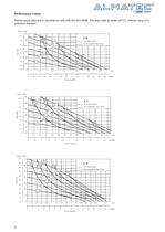
6 Performance charts Performance data are in accordance with DIN EN ISO 9906. The data refer to water (20°C), without using of a pulsation damper.
Open the catalog to page 6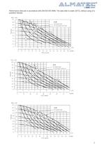
7 Performance data are in accordance with DIN EN ISO 9906. The data refer to water (20°C), without using of a pulsation damper.
Open the catalog to page 7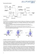
8 Recommended installation Product ports The product ports are integrated into the center housing [2]. Different port configurations can be obtained (without using of a screwed pulsation damper only). The standard configuration of the A-Series at delivery is with the suction inlet horizontally at the bottom and the discharge outlet horizontally at the top (figure 7.1). Further possible configurations: „h Suction inlet vertically at the bottom, the discharge outlet horizontally at the top (figure 7.2) To obtain this configuration, the plug of the center housing [8] has to be removed and set in...
Open the catalog to page 8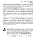
9 the line which would affect the suction lift. air filter [20] directly behind the air inlet 9] (not included in A 08 and A 10) prevents the entry of bulk particles. well valid when using a compressor producing warm air which is e.g. often true for truck ompressors. oppage, the pump must be released from the pressure within e system on both fluid side and air supply side. orque values re g bolts should be controlled more frequently (interval proposals are available on request). in The air inlet [19] is located in the middle of the center housing [2]. Before installation make sure that the air...
Open the catalog to page 9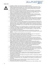
10 Safety hints „h Installation, operation, and maintenance by qualified staff only. „h Before start-up of the pump anyone should acquaint oneself with the explanations of the chapter troubleshooting (see pages 16/17). Only by this the defect quickly can be realized and eliminated in case of trouble. Problems which cannot be solved or with an unknown reason should be passed on to the manufacturer. „h Before any maintenance and service procedures arising on the pump or on the optional equipments, the complete installation has to be turned off and protected against accidental turn on. This is possible...
Open the catalog to page 10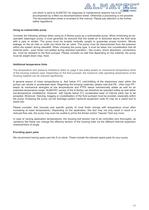
11 unit which is send to ALMATEC for diagnosis or maintenance reasons has to be accompanied by a filled out decontamination-sheet. Otherwise a processing is not possible. The decontamination-sheet is enclosed to this manual. Please pay attention to the further safety regulations. Using as submersible pump Consider the following advises when using an A-Series pump as a submersible pump: When immersing an air- operated diaphragm pump, it must generally be ensured that the waste air is deducted above the fluid level with a pipe or similar. The pump must be located vertically upright to guarantee...
Open the catalog to page 11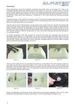
12 Disassembly When dismantling a pump the mentioned procedures and safety notes on the pages 9-11 have to be considered generally. Among the different sizes of the A-Series - A 15 to A 50 - only the number of housing bolts [15] varies. Besides, for the sizes A 08 and A 10 the shaft [16] additionally functions as the pilot piston for the air-valve. In these pumps A 08 and A 10, there are no shaft piston rings [18] and no set screws [17] nor an air filter [20]. Please keep these differences in construction in mind when reading the following dismantling instructions. The general design of the ALMATEC...
Open the catalog to page 12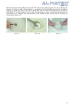
13 Remove both parts of the shaft piston rings [18] from their grooves carefully (figure 13.1); do not damage the edges in the center housing, a re-assembly of the same piston rings is impossible, they have to be replaced. Unscrew the muffler [21], the air inlet [19] and the air filter [20] out of the center housing [2]. To remove the PERSWING P® air control system, screw off both end caps using the plastic mounting tool delivered with the pump (figure 13.2). Take out main and pilot piston. Push out the air valve housing with the mounting tool turned around (figure 13.3). figure 13.1 figure 13.2...
Open the catalog to page 13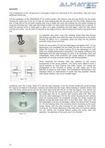
14 Assembly The re-assembly of the components is principally carried out vice-versa to the dismantling. Here are some additional references. For the installation of the PERSWING P® air control system, first screw in one end cap flushly into the center housing [2]. Insert one of the six O-rings air-valve housing [24] into the end cap from the inside. Moisture the four O-rings [24] of the air-valve housing with a bit of water and push the housing into the center housing [2] using the mounting tool. Take care that it slips in softly. Do never insert the housing violently with a hammer. In case the...
Open the catalog to page 14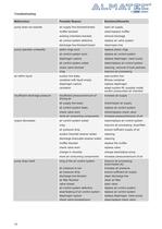
16 Troubleshooting Malfunction Possible Reason Solutions/Remarks pump does not operate air supply line blocked/closed muffler blocked working chambers blocked air control system defective discharge line blocked/closed open air supply clean/replace muffler remove blockage replace air valve system clean/open line pump operates unsteadily piston rings worn air control system worn diaphragm rupture air control system soiled check valve blocked icing replace piston rings replace air control system replace diaphragm, clean pump clean/replace air control system cleaning, removal of bulk particles improve...
Open the catalog to page 16All ALMATEC Maschinenbau GmbH catalogs and technical brochures
 CXM Series Brochure A4
6 Pages
 C- Serie
8 Pages
 FUTUR Series
8 Pages
 C-Series Brochure A4
6 Pages
 Chemicor Brochure A4
8 Pages
 Biocor Brochure A4
8 Pages
 AHD/AHS Series Brochure A4
8 Pages
 E-Series AODD Pumps
12 Pages
 Almatec brochure
16 Pages
 F-SERIES
16 Pages
 CX
CX12 Pages
 AD 6
AD 68 Pages
 AH
AH20 Pages
 FUTUR
FUTUR20 Pages
 CHEMICOR
20 Pages
 E-SERIES
12 Pages
 Decontamination-Sheet
1 Page





Archived catalogs
 Almatec Market Brochure
8 Pages