


- Products
- Catalogs
- News & Trends
- Exhibitions
Power

Power
The document outlines specifications for DeviceNet connectors and cables, including mini straight and right-angle connectors for thin and thick cables. Standard cable lengths range from 1 to 30 meters, with specific catalog numbers for each configuration.
Specifications for IP67 dynamic brake resistors are detailed, including drive and motor sizes, resistance, continuous power, maximum energy, and braking torque percentages. Application types are defined for different braking torque capabilities.
ArmorStart controllers are designed for large horsepower conveyors, featuring built-in DeviceNet communications and DeviceLogix technology. They support zone interlocking parameters for direct communication between conveyor zones, enhancing applications like merging and diverging.
The document outlines the integration of ArmorStart safety controllers with the 1732DS-IB8XOBV4 safety I/O module, forming a subsystem for machine stop functions. It includes catalog numbers for safety-related parts and configuration guidelines for the safety I/O module and PLC program.
ArmorBlock Guard I/O modules offer distributed I/O advantages for safety systems with an IP67 package. They simplify wiring and reduce startup costs by eliminating electrical boxes. The modules communicate on DeviceNet networks using CIP Safety, providing detailed diagnostics and integration with safety controllers.
The document includes detailed electrical ratings, environmental conditions, mechanical specifications, and DeviceNet communication parameters. It specifies operating temperatures, humidity, shock resistance, and EMC emission levels, ensuring compliance with various certifications.
- Mount for LCD Display: IP30, NEMA Type 1, includes a 22-RJ45CBL-C20 cable.
- DSI HIM Cables: Available in 1.0 Meter (22-HIM-H10) and 2.9 Meter (22-HIM-H30) lengths.
- Communication Adapters: Options include ControlNet, DeviceNet, EtherNet/IP, LonWorks, and PROFIBUS DP adapters.
- Serial Converter Module: Provides serial communication via DF1 protocol, includes necessary cables and software.
- Communication Option Kits: Require a Communication Adapter Cover when used with specific PowerFlex drives.
- IP30, NEMA/UL Type 1 Conversion Kit: Converts IP20 drives to IP30, includes necessary components for installation.
- DriveGuard Safe Torque-Off: Provides safety features for PowerFlex drives.
- EMC Filters: Required to meet CE certification, suitable for specific cable lengths and environments.
- PowerFlex 70 AC Drive: Offers a compact package with various features for integration and configuration, available in different voltage and power ratings.
- Dynamic Brake Resistors: Specifications for different drive ratings and resistances.
- Speed and torque control options, safety certifications, and enclosure types are detailed for various drive models.
- Kinetix 6200 and 6500: TÜV-certified up to SIL3 and PLe, embedded safety features, interchangeable control modules, and dual-channel monitoring. Compatible with Allen-Bradley motors and actuators.
- Standards and Certifications: Complies with IEC/EN 60204-1, ISO12100, IEC 61508, and others. Certified by C-Tick, CE, cUL, and TÜV.
- Power Modules: Specifications for AM and IAM power modules include continuous and peak output currents, AC/DC input voltages, and module dimensions.
- Embedded safety functions reduce panel space and wiring needs.
- Supports Safe Speed Monitoring and Safe Torque-off functionalities.
- Safety inputs and outputs are detailed, including PFd(t) and PFh(t) values for single and dual-encoder configurations.
- Kinetix 6200: Uses SERCOS interface for configuration and Ethernet for diagnostics.
- Kinetix 6500: Employs a star topology for EtherNet/IP networking, enhancing fault tolerance.
- Drive-to-drive SERCOS cables and Ethernet cables are specified for various configurations.
- Safe-off multi-axis configurations are outlined for Kinetix 6000 to 7000 drives.
The Kinetix 6000 or Kinetix 7000 drive Safe-off connector is wired to an Allen-Bradley safety relay. Proper configuration in RSLogix™ 5000 software is required. An Allen-Bradley GuardPLC™ or GuardLogix® controller can be used instead of the safety relay for more complex safety systems.
The Safe-off connector wiring involves specific connections to the Allen-Bradley Monitoring Safety Relay MSR138.1DP or MSR127RP. External 24V COM and +24V DC are used for Safe-off Demand.
Safe-off wiring headers and interface cables are available for Kinetix 6000 and 7000 drives. The configurations must not exceed eight drive modules due to current capacity limitations.
The Allen-Bradley CENTERLINE® Medium Voltage Motor Control Centers with ArcShield™ provide enhanced personnel protection by redirecting arc flash energy. ArcShield products comply with IEEE C37.20.7 standards and offer Type 2 protection during an arc flash.
Specifications include reinforced cabinet design, multi-point latching mechanisms, and arc "Pressure Relief" vents. Various controller sizes and configurations are available, with specific mounting dimensions and weight.
CENTERLINE 1500 and 2500 MCCs with ArcShield offer arc flash protection and meet IEC standards. They provide personnel and assembly protection for arcing durations up to 300 ms.
CENTERLINE 2100 and 2500 MCCs with ArcShield enhance safety by containing arc flashes and reducing electrical shock hazards. IntelliCENTER technology provides advanced diagnostics and remote access to MCC data.
Bulletin 100S/104S Safety Contactors feature mechanically linked N.C. auxiliary contacts and front-mounted auxiliary contacts with protective covers.
- Electrical, pneumatic, and hydraulic energy isolation capabilities.
- Multiple lockout points through Remote Lockout Stations (RLS).
- System Multiplexer for controlling multiple systems.
- Verification Module for interfacing with safety-gate interlocks.
- Compliance with international safety standards (EN 954-1/ISO 13849-1, TÜV certified Category 4).
- Standard system supports up to four RLS for 23-85 A systems and up to six RLS for 110-1200 A systems.
- Optional expansion modules for additional RLS connections.
- Network communication options for system status updates.
- Certifications include cULus, TÜV Rheinland, and CE marking.
- Operating temperature range: 0 to +40°C (32 to 104°F).
- Power panel construction options include NEMA Type 12/IP54 and UL Type 4/IP66.
- After stopping the machine, the operator turns the RLS handle to the OFF position, isolating the supply voltage and grounding the load.
- The system isolated light illuminates, and the operator applies a lock to the RLS.
- Communication modules available for DeviceNet, Remote I/O, ControlNet, Ethernet IP, and PROFIBUS.
- Expansion modules support additional RLS connections and can include a time-delay feature for controlled stops.
- Pneumatic and hydraulic isolation modules block energy sources and signal the power panel when isolation is achieved.
The Remote Lockout Station is a crucial part of the ElectroGuard system, typically located at the hazard site to signal the power panel to start the LOTO process. It comes in various configurations and enclosure types. The Dual RLS can control two ElectroGuard systems simultaneously, useful for machines with two power sources.
The Verification Module (VM) connects between the solenoid locking safety switch and the RLS input on an ElectroGuard system. It ensures the safety gate is locked before re-energizing the machine, providing a redundant signal to the ElectroGuard system.
This module allows simultaneous control of multiple hazards from a single lockout point. It coordinates the LOTO process with the control system, ensuring power is disconnected only at acceptable stopping points. The Permissive option allows the control system to signal when the process is at a desired stopping point.
To select the appropriate Safety Isolation System, determine the load rating, number of RLS required, and any expansion modules needed. Choose suitable enclosure types and factory-installed options based on application requirements.
Bulletin 194E load switches are designed for local motor isolation and disconnect applications. They are available in various configurations and comply with multiple standards, including UL and IEC. The switches come in different mounting styles and handle configurations, with options for padlockable handles.
- Box Lugs: Rated IP20, with mechanical life ranging from 0.075 to 0.1 million operations. Wire gauges vary, with fine strands supporting up to 150 mm² and rigid wire up to 185 mm².
- Bolt-on Terminals: Available in straight and bent versions, with specific dimensions provided for 3- and 4-pole configurations.
- Dimensions are provided in both millimeters and inches, intended for reference rather than manufacturing.
- Specific dimensions are detailed for front-installation and base-mounting configurations, including box lugs and bolt-on terminals.
- Includes information on terminal covers, door clutches, and handle types (194E-HE series).
- Additional accessories like shaft extensions and name plates are mentioned for customization and extended functionality.
- Ensure compatibility with IEC 947-1 standards for terminal sizes and wire gauges.
- Installation dimensions are critical for proper fitting and should be adhered to as specified.
Catalog excerpts
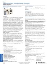
01_280_DistMotorCntl 5/13/2010 1:08 PM Page 6-2 Power Safety ArmorStart® Distributed Motor Controllers Bulletin 280D/281D 6-Distributed Motor Controllers 280D/281D ArmorStart Distributed Motor Controller — Safety Version Standards Compliance UL 508 CSA C22.2, No. 14 EN/IEC 60947-1 CCC CE Marked per Low Voltage Directive 73/23/EEC and EMC Directive 89/336/EEC Mode of Operation Full-Voltage Start This method is used in applications requiring across-the-line starting. Full in-rush current and locked-rotor torque are realized. The ArmorStart Bulletin 280 offers full-voltage starting, and the Bulletin...
Open the catalog to page 2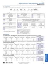
01_280_DistMotorCntl 5/13/2010 1:08 PM Page 6-3 Power Safety ArmorStart® Distributed Motor Controllers Bulletin 280D/281D 6-Distributed Motor Controllers Cat. No. Explanation Examples given in this section are for reference purposes. This basic explanation should not be used for product selection; not all combinations will produce a valid catalog number. 280 a D – F b 12S – 10 c d C – CR – Option 1 e f g h a e f Bulletin Number Short Circuit Protection (Motor Circuit Protector) Overload Selection Current Range Description Code Description 280 Full Voltage Starter Code Description B 0.5…2.5 A...
Open the catalog to page 3
01_280_DistMotorCntl 5/13/2010 1:08 PM Page 6-4 Power Safety ArmorStart® Distributed Motor Controllers Bulletin 280D/281D 6-Distributed Motor Controllers Options – Factory Installed Description Cat. No. Modification -3 Hand/Off/Auto Selector Keypad with Forward/Reverse Function Principles Hand/Off/Auto Selector Keypad -3FR Enclosure Rating Supplied without motor cable IP67 Connectivity to ArmorConnect Power Media supplied without motor cable Short Circuit Protection Rating -CRW Enclosure Rating 10 A IP67 25 A -RRW 9- Accessories Sealing Caps Description For Use With Plastic Sealing Cap (M12)1...
Open the catalog to page 4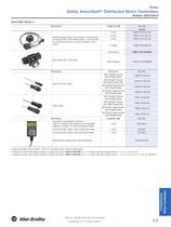
01_280_DistMotorCntl 5/13/2010 1:08 PM Page 6-5 Power Safety ArmorStart® Distributed Motor Controllers Bulletin 280D/281D Description Length [m (ft)] Cat. No. 1 (3.3) 1485P-P1E4-B1-N5 2 (6.5) 1485P-P1E4-B2-N5 3 (9.8) 1485P-P1E4-B3-N5 6 (19.8) 1485P-P1E4-B6-N5 Left Keyway 1485P-P1N5-MN5KM Right Keyway 6-Distributed Motor Controllers DeviceNet Media ♣ 1485P-P1N5-MN5NF KwikLink pigtail drops are Insulation Displacement Connector (IDC) with integral Class 1 round cables for interfacing devices or power supplies to flat cable. DeviceNet Mini- T-Port Tap Mini Straight Female Mini Right Angle Male 1485G-P...
Open the catalog to page 5
01_280_DistMotorCntl 5/13/2010 1:08 PM Page 6-6 Power Safety ArmorStart® Distributed Motor Controllers Bulletin 280D/281D 6-Distributed Motor Controllers Sensor Media ArmorStart I/O Connection Description Principles AC Micro Patchcord Input Output 5-pin 3-pin 889D-F4ACDM-® Straight Female Right Angle Male 889D-F4ACDE-® 879D-F4ACDM-® Right Angle Male 879D-R4ACM-® Straight Female Straight Male DC Micro VCable 5-pin Cat. No. Straight Female Input Connector Straight Female Straight Male DC Micro Patchcord Pin Count 889R-F3AERM-® Straight Female Right Angle Male 889R-F3AERE-® 9- See the On-Machine...
Open the catalog to page 6
01_280_DistMotorCntl 5/13/2010 1:09 PM Page 6-7 Power Safety ArmorStart® Distributed Motor Controllers Safety I/O Module and TÜV Requirements ArmorStart Safety-Related Parts Each ArmorStart Safety Distributed motor controller is intended to be combined with the 1732DS-IB8XOBV4 safety I/O module to form a subsystem that is part of the overall machine stop function. The motor controllers are connected to the safety I/O module through specified cable assemblies. The combination of one of these controllers, the safety module, and the specified interconnecting cables are referred to as the ArmorStart...
Open the catalog to page 7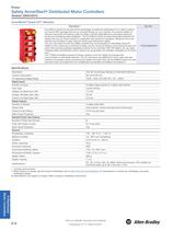
01_280_DistMotorCntl 5/13/2010 1:09 PM Page 6-8 Power Safety ArmorStart® Distributed Motor Controllers Bulletin 280D/281D 6-Distributed Motor Controllers ArmorBlock® Guard I/O™ Modules Description Cat. No. Principles ArmorBlock Guard I/O provides all the advantages of traditional distributed I/O for safety systems, but has an IP67 package that can be mounted directly on your machine. On-machine safety I/O reduces wiring time and startup costs for safety controller applications by eliminating electrical boxes and simplifying cable installation. The ArmorBlock family provides industrially hardened...
Open the catalog to page 8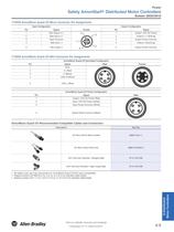
01_280_DistMotorCntl 5/13/2010 1:09 PM Page 6-9 Power Safety ArmorStart® Distributed Motor Controllers 1732DS ArmorBlock Guard I/O Micro Connector Pin Assignments Input Configuration Output Configuration Pin Signal Female 1 Test Output n+1 2 Input Common 4 Safe Input n 5 Test Output n Signal 1 5 Safe Input n+1 3 2 Pin Output +24V DC Power 2 Output n (Sourcing) 5 3 4 Output Power Common 4 1 Output n+1 (Sinking) 3 Output Power Common Principles 1732DS ArmorBlock Guard I/O Mini Connector Pin Assignments ArmorBlock Guard I/O DeviceNet Configuration Pin Signal 1 Male Drain 2 V- (Black) 4 CAN_H (White)...
Open the catalog to page 9
Safety ArmorStart® Distributed Motor Controllers External Devices powered by Control Voltage Visit our website: www.ab.com/catalogs
Open the catalog to page 10
01_280_DistMotorCntl 5/13/2010 1:09 PM Page 6-11 Power Safety ArmorStart® Distributed Motor Controllers Bulletin 280D/281D IEC -20…+40 °C (-4…+104 °F) Storage and Transportation Temperature Range –25….+85 °C (–13…+185 °F) Altitude Environmental 6-Distributed Motor Controllers UL/NEMA Operating Temperature Range 2000 m Humidity 5…95% (non-condensing) Pollution Degree Enclosure Ratings 3 NEMA 4/12/13 IP67 Approximate Shipping Weight 6.8 kg (15 lb) Resistance to Shock 15 G Non-Operational 30 G Principles Operational Resistance to Vibration Operational 1 G, 0.15 mm (0.006 in.) displacement Non-Operational...
Open the catalog to page 11
01_280_DistMotorCntl 5/13/2010 1:09 PM Page 6-12 Power Safety ArmorStart® Distributed Motor Controllers Bulletin 280D/281D 6-Distributed Motor Controllers External Connections for Input Connector Safety Monitor Input (SM1/SM2) Pin 1: +V Out Pin 2: Input Pin 3: Comm Pin 4: Input Pin 5: NC (No Connection) Pin 1: SM2 - White Pin 2: SM1 - Brown Pin 3: NC (No Connection) Pin 4: NC (No Connection) External Connections for Output Connector Principles External Connections for Safety Input Power (A1/A2) Pin 1: PE Pin 2: Return Pin 3: Relay Out Pin 1: M - White Pin 2: A1 - Brown Pin 3: P - Black Pin 4:...
Open the catalog to page 12All Allen-Bradley catalogs and technical brochures
 Circuit Breakers
12 Pages
 Micro870
4 Pages
 IntelliCENTER
12 Pages
 PowerMonitor™ 1000
2 Pages
 1608 i-Sense®
2 Pages
 Presence Sensing
9 Pages
 prxlim-br001 2014
8 Pages
 Kinetix Servo Drive Family
7 Pages
 IP67 | 280/281 series
8 Pages
 MEDIUM VOLTAGE CONTROLLERS
48 Pages
 1756 GuardLogix?
2 Pages
 max. 75 m | Lifeline 4
2 Pages
 Safety Switches
8 Pages
 PowerFlex® Low Voltage AC Drives
145 Pages
 POWER FLEX ® 70 & 700
2 Pages
 PowerFlex® 4M AC Drive
2 Pages
 PowerFlex® 520
20 Pages
 PowerFlex Family
145 Pages
 Dynamix 2500 Data Collector
2 Pages
 1492-br018
8 Pages
 Other Safety Related Products
10 Pages
 Connection Systems
30 Pages
 Logic
Logic146 Pages


Archived catalogs
 Operator Interface
54 Pages
 Safety Switches
160 Pages
 S116 Safety Products Catalog
740 Pages
 CATALOGUE SAFETY PRODUCTS
16 Pages