
- Catalogs
- Allen-Bradley
- Operator Interface


- Products
- Catalogs
- News & Trends
- Exhibitions
Operator Interface

Operator Interface
The document provides comprehensive information on operator interface devices, focusing on cable pull switches used as emergency stop devices for machinery like conveyors. These devices use a steel wire rope connected to latching pull switches to ensure machine power is cut off when the rope is pulled or goes slack.
The document details specifications for different Lifeline models:
- Lifeline 3: Made of painted zinc alloy, supports up to 30 m cable span, includes reset functionality but no E-stop.
- Lifeline 4: Made of painted aluminum alloy, supports up to 75 m cable span, includes both reset and E-stop functionalities.
- Lifeline 4 Stainless Steel: Made of stainless steel 316, supports up to 125 m cable span, includes reset and E-stop functionalities.
The document provides detailed mounting specifications for both standard and extended length models, emphasizing the importance of proper placement of P. bolts/eye bolts to ensure effective operation. It also highlights the necessity of a thorough functional test post-installation.
The LRTS is designed for quick installation of cable actuated systems, featuring a cable adjustment range of up to 300 mm, quick threading and gripping of cables, and simple tensioning using an Allen key. It is made from durable materials like glass-filled nylon and stainless steel.
The document lists various installation kits and accessories available for different cable lengths and configurations. It also provides product selection details for Lifeline 3, including contact configurations and connector options.
The Lifeline systems comply with ISO 13850 and other relevant safety standards, designed to meet high safety classifications suitable for use in performance levels Ple or Pld systems, depending on application characteristics.
1. Use a switch at both cable ends for long or complex cable runs.
2. Ensure the full length of the cable is visible during reset or inspect the entire cable length before and after resetting.
3. Conduct a thorough functional test after installation to ensure all safety functions are operational.
- Constructed from stainless steel 316, suitable for external use and environments requiring hygiene and corrosion resistance.
- Incorporates a positive mode mechanism ensuring contacts latch open upon actuation, resettable only by turning a blue knob.
- Includes a mushroom head emergency stop button for access at span ends.
- Features a cable status indicator for easy setup and maintenance over spans up to 75 meters.
- Provides four sets of contacts: 2 normally closed (N.C.) and 2 normally open (N.O.).
- Sealed to IP66 and IP69K standards for harsh conditions.
Suitable for environments requiring emergency stop access and high corrosion resistance, such as food processing or outdoor installations.
The document discusses the integration of enabling devices into machine safeguarding systems, emphasizing setting machines to reduced performance modes and ensuring the machine remains in this mode. For multiple personnel access, each person must have their own enabling device.
Outlines when additional interlocking devices are necessary, with specific configurations for partial and full body access.
The enabling switch is a three-position device used for safe working inside machine guards, ergonomically designed with three positions: no pressure (open contacts), mid-position (closed contacts), and fully pressed (open contacts).
Includes certifications and standards, operating conditions, electrical ratings, LED module ratings, and mechanical ratings. Materials used include nitrile, TPE, stainless steel, and more.
Details on push buttons, emergency stop devices, and 3-position operators, emphasizing compliance with international standards and certifications.
Lists replacement parts like relays and screws, and provides dimensions for operator interface touch buttons and wiring diagrams.
Catalog excerpts

04-OperInterface 1 5/3/2010 3:33 PM Page 4-2 Operator Interface Cable Pull Switches Overview Cable Pull Switches Overview Selection Guide General For machinery such as conveyors, it is often more convenient and effective to use a cable pull device along the hazard area (as shown in the figure below) as the emergency stop device. These devices use a steel wire rope connected to latching pull switches so that pulling on the rope in any direction at any point along its length will trip the switch to cut off the machine power. Description Lifeline 3 Lifeline 4 Stainless Steel Lifeline 4 Material...
Open the catalog to page 2
04-OperInterface 1 5/3/2010 3:33 PM Page 4-3 Operator Interface Cable Pull Switches Overview Mounting Specifications for Standard Rope Length Models E-Stop Button Tension Indicator L1 L2 Lifeline 4 300 mm (11.81 in) 75 m (246 ft) Lifeline 3 125 mm (5 in) 30 m (98 ft) Reset Knob Cable Grips Lifeline 3 General Lifeline 4 Tensioner Polypropylene-covered steel cable P. Bolts F Tension Indicator d L1 2-3m (6-9ft) 1- Reset Knob ≤ L2 Rope Grips Tensioner Eye Bolts Thimble E-Stop Button 2-Opto-electronics Polypropylene Covered Steel Rope Tension 300 (11.81) Reset Knob 2-3 m (6.5-9 ft) 75 m (246 ft) Indicator...
Open the catalog to page 3
04-OperInterface 1 5/3/2010 3:33 PM Page 4-4 Operator Interface Cable Pull Switches Lifeline™ Rope Tensioner System (LRTS) Specifications Color 4 mm (0.15 in.) Cable Adjustment Range, Max. 1- -25…80° (-13…176°) Cable O.D. 2-Opto-electronics The LRTS is a unique cable (rope) tensioning system which enables quicker installation of cable actuated systems. Other methods are traditionally time consuming and sometimes awkward to fit. Features of the system include: 1. Cable adjustment up to 300 mm (11.8 in) (150 mm (5.9 in) either side of tensioner) 2. Quick thread and grip of cable with cable grip...
Open the catalog to page 4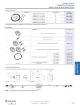
04-OperInterface 1 5/3/2010 3:33 PM Page 4-5 Operator Interface Cable Pull Switches Lifeline™ Rope Tensioner System (LRTS) Product Selection No. of P-Bolts Cat. No. 3 440E-A13079 Installation Kit—10 m (32.8 ft) 6 440E-A13080 Installation Kit—15 m (49.2 ft) 8 440E-A13081 Installation Kit—20 m (65.6 ft) 10 440E-A13082 Installation Kit—30 m (98.4 ft) 14 440E-A13083 Installation Kit—50 m (164 ft) 22 440E-A13084 Installation Kit—75 m (246 ft) 32 440E-A13085 Installation Kit—5 m (16.4 ft) General Description A stainless steel tensioner kit is available for use with the Lifeline 4 Stainless Steel, see...
Open the catalog to page 5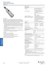
Operator Interface Cable Pull Switches The Lifeline 3 is a cable (rope) operated emergency stop device designed to meet the stringent requirements of ISO 13850 (Safety of Machinery—Emergency Stop Equipment). The Lifeline 3 system can be installed along or around awkward machinery such as conveyors and provides a constant-access emergency-stop facility. 1. The positive-mode mechanism helps ensure that the contacts are immediately latched open on actuation and can only be reset by the intentional action of turning the blue reset knob. The design also protects against nuisance tripping and the effects...
Open the catalog to page 6
04-OperInterface 1 5/3/2010 3:33 PM Page 4-7 Operator Interface Cable Pull Switches Lifeline™ 3 Product Selection Cat. No. Connectors1 Conduits Connect to ArmorBlock Guard I/O 5-Pin Micro (M12)‡ 8-Pin Micro (M12) Safety Auxiliary M20 1/2 inch NPT 12-Pin M23 2 N.C. 2 N.O. 440E-D13118 440E-D13120 440E-D13132 440E-D21BNYH 440E-D2NNNYS 3 N.C. 1 N.O. 440E-D13112 440E-D13114 440E-D13124 — General Contacts — 1 For connector ratings, see page 3-9. With an 8-pin micro (M12) connector, not all contacts are connected. See Typical Wiring Diagram on page 4-9 for wiring details. ‡ For connection to ArmorBlock...
Open the catalog to page 7
04-OperInterface 1 5/3/2010 3:33 PM Page 4-8 Operator Interface Cable Pull Switches Lifeline™ 3 Accessories Description Cat. No. 440A-A17102 Blanking plug, M20 conduit Safety Switches 440A-A17101 Lifeline outside corner pulley Outside diameter 38 mm (1.5 in.) zincplated mild steel 440A-A07265 Cable grip, M20 conduit, accommodates cable diameter 7…10.5 mm (0.27…0.41 in.) 440A-A09028 Adaptor, conduit, M20 to 1/2 inch NPT, plastic 440A-A09042 Screwdriver including security bit 2-Opto-electronics 440E-A13078 Lifeline inside corner pulley Internal diameter 16 mm (0.64 in.) zincplated mild steel 1-...
Open the catalog to page 8
04-OperInterface 1 5/3/2010 3:33 PM Page 4-9 Operator Interface Cable Pull Switches Lifeline™ 3 Typical Wiring Diagrams 2 N.C. & 2 N.O. 3 N.C. & 1 N.O. General Description Contact Configuration 12 21 22 33 34 43 44 Safety A Safety B Aux A Aux B 11 12 21 22 31 32 43 44 Safety A Safety B Safety C Aux A 1- 11 0 mm 3.5 Closed 9 0 mm Cable Tension Range 6 9 5-Pin Micro (M12) for ArmorBlock Guard I/O Cable Pulled Lockout Cable Slack Lockout Cable Tension Range 4-Safety B 3-Ground 8-Safety A 4-Safety B 2-N/A 1-Aux A — 7-Aux A 6-Safety B 5-Safety A 9 1-3 Safety A Safety B Safety B 7-8 Aux A Safety C...
Open the catalog to page 9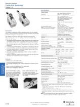
Operator Interface Cable Pull Switches The Lifeline 4 cable/push button operated system can be installed along or around awkward machinery such as conveyors and provide a constant emergency stop access. The Lifeline 4 is the only device of its kind to incorporate the following features in one unit making it the most versatile cable 1. The positive mode mechanism helps ensure that the contacts are immediately latched open on actuation and can only be reset by the intentional action of turning the blue reset knob. The design also protects against nuisance tripping and the effects of thermal 2....
Open the catalog to page 10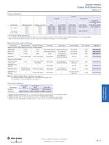
04-OperInterface 1 5/3/2010 3:33 PM Page 4-11 Operator Interface Cable Pull Switches Lifeline™ 4 Product Selection Connectors1 Cable Span 8-Pin Micro Connect to ArmorBlock Guard I/O 5-Pin Micro (M12)‡ Safety Contacts Auxiliary Contacts M20 1/2 inch NPT 12-Pin M23 2 N.C. 2 N.O. 440E-L13137 440E-L13133 440E-L13140 440E-L21BNYH 440E-L2NNNYS 3 N.C. 1 N.O. 440E-L13042 440E-L13043 440E-L13141 — — 2 N.C. 2 N.O. 440E-L13153 440E-L13155 440E-L13163 440E-L21BTYH — 3 N.C. 1 N.O. 440E-L13150 440E-L13152 440E-L13164 — General Cat. No. Conduits — 75 m (246 ft) 75…125 m (146…410 ft) 1 For connector ratings,...
Open the catalog to page 11All Allen-Bradley catalogs and technical brochures
 Circuit Breakers
12 Pages
 Micro870
4 Pages
 IntelliCENTER
12 Pages
 PowerMonitor™ 1000
2 Pages
 1608 i-Sense®
2 Pages
 Presence Sensing
9 Pages
 prxlim-br001 2014
8 Pages
 Kinetix Servo Drive Family
7 Pages
 IP67 | 280/281 series
8 Pages
 MEDIUM VOLTAGE CONTROLLERS
48 Pages
 1756 GuardLogix?
2 Pages
 max. 75 m | Lifeline 4
2 Pages
 Safety Switches
8 Pages
 PowerFlex® Low Voltage AC Drives
145 Pages
 POWER FLEX ® 70 & 700
2 Pages
 PowerFlex® 4M AC Drive
2 Pages
 PowerFlex® 520
20 Pages
 PowerFlex Family
145 Pages
 Dynamix 2500 Data Collector
2 Pages
 1492-br018
8 Pages
 Other Safety Related Products
10 Pages
 Connection Systems
30 Pages
 Power
Power166 Pages
 Logic
Logic146 Pages


Archived catalogs
 Safety Switches
160 Pages
 S116 Safety Products Catalog
740 Pages
 CATALOGUE SAFETY PRODUCTS
16 Pages
- Transformer
- Automation software solution
- Intel® Core™ PC
- Dry transformer
- HDMI PC
- Box PC
- Digital I/O
- Real-time software
- Single-pole switch
- Junction block
- IO module
- Control software
- Push-button switch
- Analog I/O
- Digital IO module
- Monitoring software solution
- Circuit breaker
- Technology switch
- Wall-mounted PC
- Servo-amplifier