
Catalog excerpts
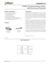
OUT1 IN4 IN5 IN6 IN7 IN8 FAULT IN3 2987 OUT2 OUT3 OUT4 OUT5 OUT6 OUT7 OUT8 IN2 IN1 4.75 to 35 V 1 to 8 Load Components CPU GND OE/R ¯ VS Description Providing overcurrent protection for each of its eight sourcing outputs, the UDN2987A-6 and UDN2987LW-6 drivers are used as an interface between standard low-level logic and relays, motors, solenoids, LEDs, and incandescent lamps. These devices include thermal shut down and output transient protection/clamp diodes for use with sustaining voltages to 35 V. In these drivers, each channel includes a latch to turn off that channel if the maximum channel current is exceeded. All channels are disabled if the thermal shutdown is activated. A common FAULT output is used to indicate either chip thermal shutdown or any overcurrent condition. All outputs are enabled by pulling the common OE/R input high. When OE/¯R is low, all outputs are inhibited and the eight latches are reset. The OE/¯R function can be especially important during power-up, in preventing floating inputs from turning on the outputs. Under normal operating conditions, each of eight outputs will source in excess of 100 mA continuously at an ambient temperature of 25°C and a supply of 35 V. The overcurrent 29876-DS, Rev. 3 Features and Benefits 4.75 to 35 V driver supply voltage Output enable-disable (OE/R) 350 mA output source current Overcurrent protected Internal ground clamp diodes Output Breakdown Voltage 35 V minimum TTL, DTL, PMOS, or CMOS compatible inputs Internal Thermal Shutdown (TSD) DABIC-5 8-Channel Source Driver with Overcurrent Protection Continued on the next page… Packages: Typical Application Not to scale UDN2987x-6 20-pin DIP 20-pin SOICW (A package) (LW package)
Open the catalog to page 1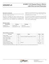
DABIC-5 8-Channel Source Driver UDN2987x-6 with Overcurrent Protection Allegro MicroSystems, Inc. 2 115 Northeast Cutoff Worcester, Massachusetts 01615-0036 U.S.A. 1.508.853.5000; www.allegromicro.com Parameter Symbol Notes Rating Units Supply Voltage VS 35 V Continuous Output Current* IOUT Outputs are disabled at approximately –500 mA –500 mA FAULT Output Voltage VCE 35 V FAULT Output Current IC 30 mA Input Voltage VIN –0.3 to 14 V Junction Temperature TJ 150 °C Storage Temperature Range TS Range N –55 to 150 °C Operating Temperature Range TA –20 to 85 °C *For input and output current...
Open the catalog to page 2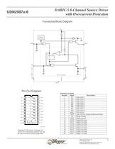
DABIC-5 8-Channel Source Driver UDN2987x-6 with Overcurrent Protection Allegro MicroSystems, Inc. 3 115 Northeast Cutoff Worcester, Massachusetts 01615-0036 U.S.A. 1.508.853.5000; www.allegromicro.com Functional Block Diagram Pin-Out Diagram Terminal List Table Number Name Description 1 IN1 Logic input 1 2 IN2 Logic input 2 3 IN3 Logic input 3 4 IN4 Logic input 4 5 IN5 Logic input 5 6 IN6 Logic input 6 7 IN7 Logic input 7 8 IN8 Logic input 8 9 FAULT Fault output 10 OE/ ¯R¯ Logic input for Output Enable and Reset 11 VS Supply voltage 12 GND Supply ground 13 OUT8 Output 8 to load 14 OUT7...
Open the catalog to page 3
DABIC-5 8-Channel Source Driver UDN2987x-6 with Overcurrent Protection Allegro MicroSystems, Inc. 4 115 Northeast Cutoff Worcester, Massachusetts 01615-0036 U.S.A. 1.508.853.5000; www.allegromicro.com ELECTRICAL CHARACTERISTICS, valid at TA = 25°C, VOER = 2.4 V, VS = 35 V, unless otherwise noted Characteristic Symbol Test Conditions Min. Typ.1 Max. Units Supply Voltage Functional Range VS 4.75 — 35 V Output Leakage Current2 IOUTCEX VIN = 0.4 V, all inputs simultaneously – 200 <–5.0 – ìA Output Sustaining Voltage VOUT(sus) IOUT = –350 mA, L = 2.0 mH 35 — — V Output Saturation Voltage...
Open the catalog to page 4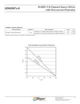
DABIC-5 8-Channel Source Driver UDN2987x-6 with Overcurrent Protection Allegro MicroSystems, Inc. 5 115 Northeast Cutoff Worcester, Massachusetts 01615-0036 U.S.A. 1.508.853.5000; www.allegromicro.com THERMAL CHARACTERISTICS Characteristics Symbol Test Conditions Rating Unit Package Thermal Resistance* RèJA Package A, on 4-layer board based on JEDEC standard 32 °C/W Package LW, on 4-layer board based on JEDEC standard 48 °C/W *Additional thermal information is available on the Allegro Web site. TA (°C) PD (W) 0 0.5 1.5 2.0 2.5 3.0 3.5 4.0 1.0 25 50 75 100 125 150 Power Dissipation versus...
Open the catalog to page 5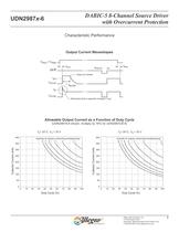
DABIC-5 8-Channel Source Driver UDN2987x-6 with Overcurrent Protection Allegro MicroSystems, Inc. 6 115 Northeast Cutoff Worcester, Massachusetts 01615-0036 U.S.A. 1.508.853.5000; www.allegromicro.com Characteristic Performance Allowable Output Current as a Function of Duty Cycle (UDN2987A-6 shown, multiply by 78% for UDN2987LW-6) TA= 25°C, VS = 35 V TA= 50°C, VS = 35 V 0 10 20 30 40 50 60 70 80 90 100 400 350 300 250 200 150 100 50 0 Duty Cycle (%) Collector Current (mA) 8 7 6 5 4 3 Quantity of outputs conducting simultaneously Output Current Waveshapes 0 10 20 30 40 50 60 70 80 90 100 400...
Open the catalog to page 6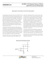
DABIC-5 8-Channel Source Driver UDN2987x-6 with Overcurrent Protection Allegro MicroSystems, Inc. 7 115 Northeast Cutoff Worcester, Massachusetts 01615-0036 U.S.A. 1.508.853.5000; www.allegromicro.com Applications Information and Circuit Description As with all power integrated circuits, the UDN2987A-6 and UDN2987LW-6 have a maximum allowable output current rating. The 500 mA rating does not imply that operation at that value is permitted or even obtainable. The channel output current trip point is specified as –370 mA, minimum; therefore, attempted operation at current levels greater than...
Open the catalog to page 7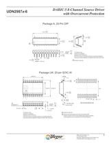
DABIC-5 8-Channel Source Driver UDN2987x-6 with Overcurrent Protection Allegro MicroSystems, Inc. 8 115 Northeast Cutoff Worcester, Massachusetts 01615-0036 U.S.A. 1.508.853.5000; www.allegromicro.com Package A, 20-Pin DIP SEATING C PLANE 5.33 MAX 0.46 ±0.12 6.35 +0.76 –0.25 26.16 +0.76 –1.27 3.30 +0.51 –0.38 10.92 +0.38 –0.25 1.52 +0.25 –0.38 7.62 2.54 0.25 +0.10 –0.05 1 2 20 A For Reference Only Dimensions in millimeters (reference JEDEC MS-001 AD) Dimensions exclusive of mold flash, gate burrs, and dambar protrusions Exact case and lead configuration at supplier discretion within limits...
Open the catalog to page 8All ALLEGRO MICROSYSTEMS catalogs and technical brochures
-
A1340
42 Pages
-
A1324
12 Pages
-
A1318
12 Pages
-
A1308
12 Pages
-
A1304
10 Pages
-
A1367
27 Pages
-
A1366
22 Pages
-
A1365
32 Pages
-
ACS770
29 Pages
-
ACS758
22 Pages
-
ACS761
14 Pages
-
A1301 and A1302
10 Pages
-
ACS709
17 Pages
-
ACS716
22 Pages
-
ACS715
14 Pages
-
ACS714
18 Pages
-
ACS712
15 Pages
-
ACS713
14 Pages
-
ACS756
11 Pages
-
ACS710
23 Pages
-
ACS711
16 Pages
-
A1360, A1361, and A1362
26 Pages
-
ACS759
19 Pages
-
Advances in WLED/RGB LED Drivers
13 Pages
Archived catalogs
-
A6261: Protected LED Array Driver
14 Pages
-
Current Sensors
9 Pages


