
- Catalogs
- ALLEGRO MICROSYSTEMS
- Sanken Semiconductors General Catalog

- Products
- Catalogs
- News & Trends
- Exhibitions
Sanken Semiconductors General Catalog

Sanken Semiconductors General Catalog
- STR-A6100 Series: Features low noise and low standby power with a SIP8 package. Includes models like STR-V152 and STR-V153 with different fixed off-time periods and MOSFET specifications.
- STR-Y6700 Series: Quasi-resonant type with high efficiency across full load range, low noise, and low standby power. Models include STR-Y6735, STR-Y6753, and others with varying VDSS and RDS(ON) values.
- STR-Y6400 Series: Similar features to the Y6700 series with adjustable mode change delay time. Includes models like STR-Y6453 and STR-Y6473.
- STR-L6400 and STR-L400 Series: Focus on low height and creepage isolation, high efficiency, and low noise. Models include STR-L6472 and STR-L451.
- STR-W6700 and STR-X6700 Series: Emphasize high efficiency, low noise, and undervoltage lockout (UVLO) standby function. Models like STR-W6734 and STR-X6737 offer features like auto burst operation and bottom-skip QR operation.
- Single Output: Various models with different output currents and voltages, such as SI-8000W and SI-8000JD series. Features include high efficiency, surface-mount packages, and built-in protection circuits.
- Multi Output: Models like STA801M and SPI-8001TW offer variable output voltages and built-in flywheel diodes.
- Mounting Torque: Specific torque values are recommended for models like SI-8000E and SI-8000JF.
- Silicone Grease Recommendations: Specific products are recommended to ensure device longevity.
- Heat Dissipation and Reliability: Emphasizes the importance of proper thermal management and the impact of temperature on component reliability.
- Internal Power Dissipation: Formulas provided for calculating power dissipation based on device specifications.
- Thermal Design: Guidelines for designing heatsinks and ensuring adequate heat dissipation.
- Operating Temperature Range: -30°C to +125°C for SI-8000JD and -20°C to +85°C for SI-8000TM.
- Input Voltage Range: Varies by model, with a minimum of VO+3V to a maximum of 40V.
- Output Current: Up to 1.5A.
- Efficiency: Ranges from 77% to 88% for SI-8000JD and 81% for SI-8000TM.
- Oscillation Frequency: 125 kHz for SI-8000JD and 300 kHz for SI-8000TM.
- Surface-mount package (TO263-5 for SI-8000JD and TO252-5 for SI-8000TM).
- High switching frequency allows for downsizing of choke-coils.
- Built-in foldback-overcurrent and thermal protection circuits.
- Output ON/OFF control with a maximum circuit current of 200µA when off.
- Soft start functionality available via the ON/OFF pin.
- Power supplies for telecommunication equipment.
- Onboard local power supplies.
- AV and OA equipment.
- Output Voltage: Varies by model, with typical values of 3.30V, 5.00V, 9.00V, and 12.00V for SI-8000JD.
- Line and Load Regulation: Maintains stability across varying input voltages and loads.
- Temperature Coefficient: ±0.5 mV/°C for output voltage stability.
- Thermal design must consider the junction temperature, which should remain below 125°C during operation.
- Efficiency is dependent on input voltage and output current, requiring careful selection of components for optimal performance.
- Block diagrams and typical connection diagrams are provided for both series, illustrating the pin assignments and recommended external components.
- Reference data includes graphs showing the relationship between copper laminate area and thermal resistance, as well as output current versus power dissipation.
- NR885K/NR885E: These models feature a compact surface-mount package, input voltage range from VO + 3 to 18 V, synchronous rectifier mode, high efficiency of 90%, and a current mode control. They support an output current of 3 A and have a reference voltage accuracy of 0.8 V ± 2%.
- SI-8205NHD/SI-8205NHG: These models offer a wide input voltage range from Vo + 3 to 43 V, synchronous rectifier mode, and an output current of 3 A. They have a reference voltage accuracy of 0.5 V ±1% and support externally synchronized frequency from 300 kHz to 1 MHz.
- SI-8000SD Series: This series supports a DC input voltage range of 5.5 to 40 V, output current of 3 A, and high efficiency up to 84%. It includes built-in overcurrent and thermal protection circuits.
- All models are designed for high efficiency and compact size, suitable for surface-mount applications.
- They include features like soft start, undervoltage lockout, and output ON/OFF control.
- Built-in protection mechanisms such as overcurrent and thermal protection ensure reliability.
- These ICs are used in power supplies for LCD modules, notebook PCs, telecommunication equipment, and onboard local power supplies.
- Input Voltage Range: Varies by model, generally from 4.5 V to 50 V.
- Output Current: Up to 3 A for all models.
- Efficiency: Ranges from 79% to 91% depending on the model and conditions.
- Operating Temperature Range: Typically from -40°C to +85°C.
- Use of low-ESR ceramic output capacitors is recommended for stability.
- Ensure proper thermal management to maintain efficiency and prevent overheating.
- Follow recommended operating conditions to ensure optimal performance and longevity of the ICs.
- DC Input Voltage Range: Varies by model, with a minimum of Vo+3V or a specified voltage, whichever is higher.
- Output Voltage Range: 0.5V to 24V depending on the model.
- Output Current Range: Up to 5.5A for certain models.
- Operating Temperature Range: -30°C to +125°C for most models.
- Reference Voltage: Typically around 0.5V to 1V.
- Efficiency: Up to 90% depending on the model and conditions.
- Oscillation Frequency: Ranges from 150 kHz to 500 kHz.
- Line and Load Regulation: Specified for each model to ensure stable output under varying conditions.
- Compact surface-mount packages.
- Built-in soft start and on/off functions.
- High efficiency and low current consumption during off states.
- Built-in overcurrent and thermal protection circuits.
- DVD recorders and FPD-TVs.
- Onboard local power supplies.
- OA equipment such as printers.
- Use of Schottky-barrier diodes for D1 to prevent IC damage.
- Selection of capacitors and resistors to ensure optimal performance and stability.
- Thermal management to prevent overheating and ensure reliable operation.
The document outlines the absolute maximum ratings for various parameters such as input voltage, power dissipation, junction temperature, and thermal resistance. For instance, the maximum input voltage is 43V, and the junction temperature can reach up to +150°C. The thermal resistance from junction to case is 3°C/W, and from junction to ambient air is 33.3°C/W.
The recommended operating conditions specify the input voltage range, output voltage range, output current range, and temperature ranges for operation. For the SI-8008HD, the input voltage range is Vo+3V to 40V, and the output voltage range is 0.8V to 24V. The operating temperature range is from -30°C to +85°C.
This section provides detailed electrical characteristics such as output voltage, efficiency, oscillation frequency, line regulation, and load regulation. For example, the output voltage for the SI-8008HD is typically 0.800V, with an efficiency of 83% at VIN=15V and Io=1A.
The document highlights features of the SI-8000 series, including a compact full-mold package, high efficiency (up to 88%), and built-in protection circuits. The series requires only four discrete components and includes a built-in reference oscillator.
The SI-8000 series is suitable for power supplies in telecommunication equipment and onboard local power supplies.
The document includes block diagrams and typical connection diagrams for the SI-8000 series, illustrating the pin assignments and external components required for operation.
Dimensions for the TO263-5 and TO220F-5 packages are provided, detailing the size and pin assignments for the components.
The document includes notes on the use of the SS pin for soft start and ON/OFF functions, emphasizing the importance of limiting current to protect the transistor when using large capacitance values.
- Input Voltage Range: 8 to 50V for SI-8010GL, 5.5 to 40V for SI-8000S series.
- Output Voltage Range: 1 to 14V for SI-8010GL, specific fixed outputs for SI-8000S series (3.3V, 5V, 9V, 12V, 15V).
- Output Current: Up to 1.5A for SI-8010GL, 3A for SI-8000S series.
- Efficiency: Up to 90% depending on the model and conditions.
- Oscillation Frequency: 250kHz for SI-8010GL, 60kHz for SI-8000S series.
- High efficiency and compact design suitable for onboard local power supplies and other applications.
- Built-in overcurrent and thermal protection circuits.
- Soft start function to prevent inrush current at startup.
- Output ON/OFF control for power management.
- Ensure the output current is above 20mA to maintain stability.
- Use high-frequency, low-impedance capacitors for C1 and C2 to handle ripple currents effectively.
- For the soft start function, connect a capacitor to the SS pin, ensuring it is not exposed to external voltage.
- Onboard local power supplies.
- Stabilization of secondary-side output voltage in switching power supplies.
- Power supplies for telecommunication equipment and consumer electronics like LCD TVs and DVD players.
- Use Schottky-barrier diodes to prevent IC damage from reverse voltage.
- Ensure proper thermal management, especially for components like the choke coil and diode D1.
- Place components close together to optimize performance and minimize interference.
- Electrical Characteristics: The document lists parameters such as quiescent circuit current, high and low-level voltages, inflow current, and efficiency calculations. It provides typical, minimum, and maximum ratings for different models under specified conditions.
- Efficiency Calculation: Efficiency is calculated using the formula η (%) = (VO·IO × 100) / (VIN·IIN), where VO is the output voltage, IO is the output current, VIN is the input voltage, and IIN is the input current.
- Absolute Maximum Ratings: Includes control-system DC input voltage, DC input voltage, boost block input voltage, and junction temperature limits.
- Soft Start and ON/OFF Functions: The document explains the use of SS pins for soft start and output control, emphasizing the need to limit discharge currents to protect transistors.
- Component Selection: Recommendations for using Schottky-barrier diodes, closed-magnetic-path coils, and high-frequency capacitors to ensure optimal performance and prevent damage.
- Thermal Design: Emphasizes the importance of heat dissipation and provides guidelines for calculating internal power dissipation and setting DC input voltage.
- Power supplies for notebook PCs and mobile devices.
- Onboard local power supplies and OA equipment.
- Stabilization of secondary-side output voltage in switching power supplies.
- Ensure proper component placement to optimize operating conditions.
- Use appropriate diodes and capacitors to prevent abnormal oscillations and ensure efficiency.
- Follow thermal design guidelines to maintain reliability and prevent overheating.
- Determine the maximum ambient temperature (Ta(max)).
- Determine the maximum power dissipation (PD(max)).
- Use the Ta-PD characteristic graph to find the appropriate heatsink size.
- Apply a 10-20% derating factor in practical applications.
- Measure heatsink and case temperature in the actual environment for accuracy.
- Series Name: SI-3000LU, NR301E, SI-3000LSA, etc.
- Diodes: AM01Z, RM10Z, SJPM-H4 with specific voltage and current ratings.
- Mounting Torque for SI-3000KF: 0.588 to 0.686 N•m.
- Recommended Silicone Grease: Shin-Etsu G746, Momentive YG-6260, Dow Corning SC102.
- Devices cannot be operated in parallel for increased current.
- Isolation diodes are provided to prevent reverse bias damage.
- Features: Compact package, low dropout voltage, built-in protection circuits.
- Applications: Auxiliary power supplies, battery-driven equipment.
- Electrical Characteristics: Includes parameters like reference voltage, dropout voltage, line regulation, etc.
- Input Voltage: 2.7V to 27V.
- Output Current: Up to 1A.
- Operating Temperature: -30°C to +125°C.
- Use low ESR capacitors for output stability.
- Enlarge copper laminate area for improved heat dissipation.
- Calculate junction temperature using specific formulas provided.
This document provides technical specifications and features for a series of integrated circuits (ICs) designed for stepper motor control. The ICs include built-in current sense resistors and protection circuits, supporting various power supply voltages and output currents.
Specifications
- Temperature Range: Storage temperature ranges from -30°C to +150°C.
- Power Supply Voltages: VBB (motor supply) ranges from 10V to 44V, with a maximum of 46V. VDD (logic supply) ranges from 3.0V to 5.5V.
- Output Currents: Maximum output currents are 1A, 1.5A, 2A, and 3A, depending on the model.
- Package Type: ZIP type 23-pin molded package (SLA package).
Features
- Built-in sequencer and self-excitation PWM current control with fixed off-time.
- Synchronous PWM chopping function to prevent motor noise in Hold mode.
- Sleep mode to reduce IC input current in standby state.
Recommended Operating Conditions
- Motor Supply Voltage (VM): Up to 44V.
- Driver Supply Voltage (VBB): 10V to 44V.
- Logic Supply Voltage (VDD): 3.0V to 5.5V.
- Case Temperature (TC): Up to 90°C.
Electrical Characteristics
- Includes parameters such as main supply current, logic supply current, output MOSFET breakdown voltage, and more.
- Specific conditions and ratings are provided for each parameter, ensuring optimal performance and safety.
Pin Assignment and Internal Block Diagram
- Detailed pin assignments are provided for various functions such as phase outputs, current sense, and control inputs.
- The internal block diagram illustrates the IC's architecture, including components like the sequencer, sleep circuit, and PWM control.
Connection and Dimensions
- Typical connection diagrams are provided for integrating the IC into motor control systems.
- External dimensions are specified for the ZIP23 package, ensuring compatibility with design requirements.
Absolute Maximum Ratings
- Defines the limits for parameters such as motor supply voltage, driver supply voltage, output current, and junction temperature.
- Emphasizes the importance of not exceeding the junction temperature under any circumstances.
- Specifications: The document outlines the absolute maximum ratings and electrical characteristics for ICs, including parameters such as supply voltage (VBB), output current (Iout), and junction temperature (Tj). It specifies the conditions under which these ratings apply, such as ambient temperature and duty cycle.
- Electrical Characteristics: Detailed tables provide minimum, typical, and maximum values for various parameters, including logic input voltage, charge pump voltage, and MOSFET on-resistance. These characteristics are crucial for ensuring the ICs operate within safe and efficient limits.
- Protection Features: The ICs include built-in protection mechanisms such as overcurrent protection (OCP), undervoltage lockout (UVLO), and thermal shutdown (TSD). These features help prevent damage to the ICs and connected components under fault conditions.
- Pin Assignments and Diagrams: The document includes pin assignment diagrams and internal block diagrams for different IC models, such as the SI-6633M and SPI-6631M. These diagrams help in understanding the IC's functionality and assist in designing circuits.
- Recommended Operating Conditions: The document specifies the recommended operating conditions for the ICs, including supply voltage ranges and ambient temperature limits. Adhering to these conditions ensures optimal performance and longevity of the ICs.
- Features: The ICs offer features like built-in synchronous rectifier functions, error detection outputs, and various control functions for current and speed regulation. These features enhance the versatility and efficiency of the motor driver applications.
- Voltage and Current Ratings: The control supply voltage ranges from 10 to 30V, with logic input voltage between 3 to 5.5V. The main supply current is 10 to 20 mA during operation and 50 to 200 μA in standby mode.
- Output Drivers: The high side and low side output voltages range from 6 to 9V, with a drive current of 20 to 60 mA.
- Protection Features: Includes overcurrent, overvoltage, thermal protection, and undervoltage lockout. The thermal protection operates at temperatures between 151 to 185°C.
- Current Control: Supports peak current control with fixed frequency PWM and logic PWM based on input.
- Protection Functions: Overcurrent, overvoltage, thermal protection, and motor lock detection are integrated.
- Alarm Output: Provides an alarm output pin for protection function operation.
- Synchronous Rectifier Function: Reduces power dissipation with built-in switching for active/passive operation.
- Operating Conditions: Recommended operating conditions include a main supply voltage of 24V and a logic supply voltage of 5V.
- External Components: Capacitors should be attached near the IC to manage noise, and external resistors may be needed to stabilize input signals.
The document provides detailed specifications for various LED driver ICs, including parameters such as drain-source voltage, drain leakage current, on resistance, switching time, and thermal resistance. It also outlines the electrical characteristics and absolute maximum ratings for different models like LC5510, LC5550, LC5560, and LC5520 series.
Procedures:
The document includes typical connection diagrams and pin functions for the ICs, detailing how each pin should be connected and its function in the circuit. It also provides guidelines for startup operation, normal operation, and protection operation.
Standards and Norms:
The ICs comply with the Harmonics Standard (ICE61000-3-2 Class C) at all load conditions, ensuring they meet international standards for electromagnetic compatibility.
Recommendations:
The document recommends using these ICs for LED light bulbs and LED lighting equipment, highlighting their features such as built-in ON time control circuit, soft start function, bias assist function, and various protection functions like overcurrent, overvoltage, overload, and thermal shutdown.
Key Features:
- Non-isolated type
- Built-in ON time control circuit for high power factor
- Built-in soft start and bias assist functions
- Protection functions including OCP, OVP, OLP, and TSD
Applications:
The ICs are suitable for LED lighting applications, providing efficient power management and protection features to enhance the performance and reliability of LED lighting systems.
- Isolated type with built-in ON time control circuit for high power factor.
- Soft start function to reduce load on power MOSFET and rectifier diodes at power-on.
- Bias assist function to improve startup and suppress VCC voltage drop.
- Leading edge blanking and maximum ON time control circuits.
- Protection functions include overcurrent, overvoltage, overload, and thermal shutdown.
- LED light bulbs and lighting equipment.
- Thermal resistance between MOSFET channel and case is specified for different models.
- Electrical characteristics are provided for various parameters such as startup voltage, supply current, and oscillation frequency.
- Absolute maximum ratings include parameters like drain current, avalanche energy capacity, and operating temperature ranges.
- Detailed pin functions for LC552xD (DIP8) and LC552xF (TO220F-7) packages are provided, including control circuit power input, overcurrent protection, and feedback signal input.
- Characteristics are specified at Ta = 25°C, with parameters like PWM oscillation frequency, maximum ON time, and feedback current detailed for different models.
- Input voltage range from 9 to 46 V, output current up to 2.0 A, and operating temperature range from -40 to 85°C.
- Diagrams illustrate typical connections and internal block structures for the ICs, aiding in understanding their operation and integration into LED lighting systems.
- DC/DC Converter ICs: These are surface mount integrated circuits used for converting direct current (DC) from one voltage level to another. They are essential in power management for electronic devices.
- Linear Regulator ICs: These ICs are used to maintain a constant output voltage regardless of changes in the input voltage or load conditions. They are available in both surface mount and standard configurations.
- Diodes: The document lists various types of diodes, including Schottky Barrier Diodes, Fast Recovery Diodes, Ultrafast Recovery Diodes, and Rectifier Diodes. These components are crucial for directing current flow and protecting circuits from voltage spikes.
- Motor Driver ICs: High and low voltage 3-phase motor driver ICs are included, which are used to control the operation of motors in various applications.
- Transistors and Thyristors: These components are used for switching and amplifying electronic signals. The document lists several models with different specifications.
- Part Numbers: Each component is associated with a specific part number, which is crucial for identification and procurement.
- Page References: The document includes page numbers for each component, facilitating easy navigation and reference.
Catalog excerpts
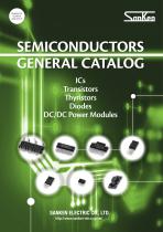
Sanken Electric Co., Ltd. Overseas Sales Headquarters Metropolitan Plaza Building, 1-11-1 Nishi-Ikebukuro Toshima-ku, Tokyo 171-0021, Japan Te l : 81-3-3986-6164 Fax: 81-3-3986-8637 WORLDWIDE SALES OFFICES Asia-Pacific China Sanken Electric Hong Kong Co., Ltd. SEMICONDUCTORS GENERAL CATALOG 2013 Suite 1026 Ocean Centre, Canton Road Tsimshatsui, Kowloon, Hong Kong Te l : 852-2735-5262 Fax: 852-2735-5494 Sanken Electric (Shanghai) Co., Ltd. Room 3202, Maxdo Centre, Xingyi Road 8 Changning District, Shanghai, China Te l : 86-21-5208-1177 Fax: 86-21-5208-1757 Sanken Electric (Shanghai) Co., Ltd. Shenzhen Office Room 1013, Xinhua Insurance Building, Mintian Road, Futian District, Shenzhen City, Guangdong, China Tel : 86-755-8283-6685 Fax: 86-755-8826-3053 Taiwan Sanken Electric Co., Ltd. Room 1801, 18th Floor, 88 Jung Shiau East Road Sec. 2, Taipei 100, Taiwan R.O.C. Te l : 886-2-2356-8161 Fax: 886-2-2356-8261 Korea Sanken Electric Korea Co., Ltd. (Yeouido B/D 16F)24,Gukjegeumyung-ro 2-gil, Yeongdeungpo-gu,Seoul 150-734, Korea Te l : 82-2-714-3700 Fax: 82-2-3272-2145 Singapore Sanken Electric Singapore Pte. Ltd. 152 Beach Road, #10-06 The Gateway East, Singapore 189721 Te l : 65-6291-4755 Fax: 65-6297-1744 Malaysia Sanken Electric (Malaysia) Sdn. Bhd. Block B-20-5, Level 20, Northpoint Midvalley City, No.1, Medan Syed Putra Utara, 59200 Kuala Lumpur, Malaysia Te l : 60-3-2282-2345 Fax: 60-3-2282-6345 Europe United Kingdom Sanken Power Systems (UK) Ltd. Pencoed Technology Park Pencoed, Bridgend CF35 5HY, United Kingdom Te l : 44-1656-869-100 Fax: 44-1656-869-162 SEMICONDUCTORS GENERAL CATALOG ICs Transistors Thyristors Diodes DC/DC Power Modules North America United States Allegro MicroSystems, Inc. 115 Northeast Cutoff Worcester, Massachusetts 01606, U.S.A. Te l : 1-508-853-5000 Fax: 1-508-853-7895 This is notification that you, as purchaser of the products/technology, are not allowed to perform any of the following: 1. Resell or retransfer these products/technology to any party intending to disturb international peace and security. 2. Use these products/technology yourself for activities disturbing international peace and security. 3. Allow any other party to use these products/technology for activities disturbing international peace and security. Also, as purchaser of these products/technology, you agree to follow the procedures for the export or transfer of these products/technology, under the Foreign Exchange and Foreign Trade Law, when you export or transfer the products/technology abroad. SANKEN ELECTRIC CO., LTD. http://www.sanken-ele.co.jp/en/
Open the catalog to page 1
Warning ● The contents in this document are subject to changes, for improvement and other purposes, without notice. ● Be sure to check the delivery specifications before using these products. ● The operation and circuit examples in this document are provided for reference purposes only. Sanken assumes no liability for violation of industrial property, intellectual property, or other rights of Sanken or third parties, that stem from these examples. ● The user must take responsibility for considering and determining which objects the products in this document are used with. ● Although we will continue...
Open the catalog to page 2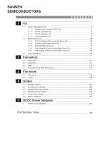
DC/DC Power Modules 5
Open the catalog to page 3
Low Voltage 3-Phase Brushless Motor Driver ICs .. 114 High Voltage 3-Phase Brushless Motor Driver ICs .. 120
Open the catalog to page 4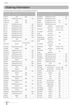
All products listed must be ordered in standard packing increments.
Open the catalog to page 5
1-1 Power Management ICs 1-1-1 Power Factor Correction (PFC) ICs Control ICs ●Continuous Conduction Mode (CCM) PFC Control IC For high power and high efficiency applications, with brown-in and brown-out functions ● Interleaved Discontinuous Conduction Mode (DCM) PFC Control IC 8-pin package, minimum number of discrete components, low noise, and low ripple Part Number Oscillation Frequency Fixed to 65kHz Series Name Series Name Part Number 1-1-2 AC/DC Converter ICs ●PWM type • For small power applications • Low noise, low standby power (Input power PIN<15mW at no load) Part Number Oscillation...
Open the catalog to page 7
1-1-2 AC/DC Converter ICs • Low noise, low standby power (Input power PIN<30mW at no load) • Brown-in and brown-out functions MOSFET Oscillation Frequency Part Number • Low noise, low standby power (Input power PIN<40mW at no load) • External latch protection (ELP) function MOSFET Oscillation Frequency Part Number ●Pulse ratio control (PRC) type with off-time period fixed (originated by Sanken Electric) • For small power applications • Low noise, low standby power Part Number Fixed off-time period Auto standby function • Low height, at least 4 mm of creepage isolation between high and low terminal...
Open the catalog to page 8
1-1-2 AC/DC Converter ICs • Low height, at least 6.5 mm of creepage isolation between high and low terminal tips • High efficiency in full load range, low noise, and low standby power • SIP10 package version of STR-Y6400 Part Number • Low height, at least 6.5 mm of creepage isolation between high and low terminal tips • Low noise, high efficiency Part Number • High efficiency in full load range • Low noise, undervoltage lockout (UVLO) standby function Part Number Auto burst operation Auto burst operation • High efficiency in full load range • Low noise, undervoltage lockout (UVLO) standby function...
Open the catalog to page 9
Selection Guide Surface-Mount Type Output Voltage (V) Variable (Reference Voltage) (V) Maximum Input Voltage Oscillation Frequency Output Current Series Name Current mode control Current mode control Current mode control, synchronous rectifier Current mode control, synchronous rectifier Current mode control, synchronous rectifier Current mode control, external synchronization Current mode control Current mode control Current mode control Thru-Hole Type Output Current Variable (Reference Voltage) (V) 15 Maximum Input Voltage Oscillation Frequency Non-package type With coil and built-in diode Non-package...
Open the catalog to page 10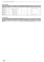
1-1-3 DC/DC Converter ICs Output Current Output Voltage Maximum Input Voltage Oscillation Frequency Part Number Built-in flywheel diode Variable (Reference Voltage) Maximum Input Voltage Oscillation Frequency Remarks Synchronous rectifier, PRC (fixed to ton)
Open the catalog to page 11All ALLEGRO MICROSYSTEMS catalogs and technical brochures
 A1340
A134042 Pages
 A1324
A132412 Pages
 A1318
A131812 Pages
 A1308
A130812 Pages
 A1304
A130410 Pages
 A1367
A136727 Pages
 A1366
A136622 Pages
 A1365
A136532 Pages
 ACS770
29 Pages
 ACS758
22 Pages
 ACS761
14 Pages
 A1301 and A1302
10 Pages
 ACS709
17 Pages
 ACS716
22 Pages
 ACS715
14 Pages
 ACS714
18 Pages
 ACS712
15 Pages
 ACS713
14 Pages
 ACS756
11 Pages
 ACS710
23 Pages
 ACS711
16 Pages
 A1360, A1361, and A1362
26 Pages
 ACS759
19 Pages
 Advances in WLED/RGB LED Drivers
13 Pages


Archived catalogs
 A6261: Protected LED Array Driver
14 Pages
 Current Sensors
9 Pages


- Proximity switch
- Single-pole switch
- Technology switch
- Position transducer
- Multipole switch
- Motor controller
- Linear position transmitter
- Analog position transducer
- No-contact position sensor
- Stepper motor controller
- Magnetic position sensor
- Bipolar switch
- Industrial position sensor
- Magnetic proximity sensor
- Speed controller
- Angular position sensor
- Proximity sensor with switching function
- Magnetic speed sensor
- Rotational speed sensor