- Catalogs
- ALLEGRO MICROSYSTEMS
- A New Microstepping Motor-Driver IC with Integrated Step and Direction Translator Interface
A New Microstepping Motor-Driver IC with Integrated Step and Direction Translator Interface
1 /9Pages

A New Microstepping Motor-Driver IC with Integrated Step and Direction Translator Interface
1 /9Pages
Catalog excerpts
Product Information A New Microstepping Motor-Driver IC with Integrated Step and Direction Translator Interface Abstract A new series of microstepping motor driver integrated circuits with an integrated step and direction translator interface has been developed specifically by to drive bipolar stepper motors. These new ICs incorporate several unique design features, including automatic mixed-mode current decay control, PWM current control, synchronous rectification, low rDS(on) power DMOS outputs, full-, half-, quarter-, eighth-, and sixteenth-step operation, HOME output, sleep mode, and an easy-to-implement step and direction interface. Introduction Most microstepping motor drivers require control lines for DACs to set the reference for the PWM current regulator and PHASE inputs for current polarity control. In more sophisticated drivers there are also inputs required for the PWM current-control mode to operate in slow, fast, or mixed decay. These control lines can quickly add up to eight to twelve inputs depending on the DAC resolution and have to be supplied by the system microprocessor. The requirement of this many control inputs, and complex sequencing tables in the microprocessor will add to the cost and complexity of the system. The A3977 and A3979 (figure 1), solve this problem with its simple two-line STEP and DIRECTION interface and an efficient DMOS output, all in one IC. For each transition in the STEP input the driver sequences one microstep. This is ideal for applications where a complex microprocessor controller is unavailable or overburdened. A stepper motor system will have reduced audible noise if the microstepping driver can switch between slow-decay and mixed-decay mode PWM operation. The A3977 and A3979 include circuitry that automatically sets the current decay mode either slow or mixed decay, which eliminates the need for the user to provide additional control lines. In order to satisfy high-end applications that require low power dissipation, the A3977/79 uses low rDS(on) n-channel power DMOS outputs rated at ±2.5 A and 35 V. Another benefit of the DMOS outputs is the ability to implement synchronous rectification. The A3977/79 synchronous- rectification control circuitry will turn on the appropriate output DMOS device during the current decay and effectively short out the body diodes with the low rDS(on) driver. This results in significantly lower power dissipation and eliminates the need for external Schottky diodes in most applications. The A3977 and A3979 are truly next-generation microstepping motor-driver ICs combining low-power dissipation and high-current outputs, efficient current control, and a simpleto-use interface. These design features and their resulting benefits are discussed in further detail below. Functional Description Microstepping Translator The A3977/79 translator converts the STEP and DIRECTION inputs into the control signals required to sequence the current in each of the two H-bridge outputs for full-, half-, quarter-, eighth- (3977 only), and sixteenth-step (3979 only) microstepping operation of a bipolar stepper motor. At power up or reset the translator sets the DACs and phase current polarity to the initial HOME state conditions and sets the current regulator for both phases to mixed-decay mode (see table 2 and figures 2 through 5 for home-state conditions). When a step command signal (logic Low-toHigh transition of the STEP input) occurs the translator automatically sequences the DACs to the next level and current polarity. Table 2 shows the current sequence table for
Open the catalog to page 1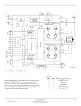
CHARGE PUMP LOAD SUPPLY MIXED DECAY PWM TIMER MS 2 HOME SLEEP VPFD GATE DRIVE CONTROL LOGIC PWM LATCH BLANKING MIXED DECAY Figure 1. A3977 Functional Block Diagram motor operation (DIRECTION input logic Low). For the reverse operation the DIRECTION input is set to logic High and the translator reverses the sequence through table 2. The DAC outputs are used by the PWM current regulator to set the trip point of the current output of each phase. The (micro)step resolution is set by inputs MS1 and MS2 as shown in table 1. Microstepping Resolution Full Step (2 phase) Half Step Quarter Step Allegro...
Open the catalog to page 2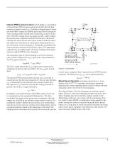
Internal PWM Current Control Each H-bridge is controlled by a fixed-off-time PWM current-control circuit that limits the load current to a desired value (ITRIP). Initially, a diagonal pair of source and sink DMOS outputs are enabled and current flows through the motor winding and the current-sense resistor (RS) as shown in figure 6. When the voltage across RS equals the DAC output voltage, the current-sense comparator resets the PWM latch, which turns off either the source drivers (slow-decay mode) or both the source and sink drivers (fast-decay or mixed-decay modes) and the current recirculates...
Open the catalog to page 3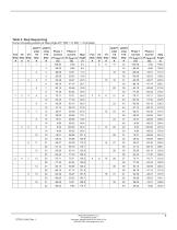
Table 2. Step Sequencing Home microstep position at Step Angle 45º; DIR = H; 360° = 4 full steps (A3977 (A3979 only) only) Phase 1 Phase 2 Full 1/2 1/4 1/8 1/16 Current Current Step Step Step Step Step Step [% Itripmax] [% Itripmax] Angle # # # # # (%) (%) (º) 1 1 1 1 100.00 0.00 0.0 2 (A3977 (A3979 only) only) Phase 1 Phase 2 Full 1/2 1/4 1/8 1/16 Current Current Step Step Step Step Step Step [% Itripmax] [% Itripmax] Angle # # # # # (%) (%) (º) 5 9 17 33 –100.00 0.00 180.0 Allegro MicroSystems, LLC 115 Northeast Cutoff Worcester, Massachusetts 01615-0036 U.S.A. 1.508.853.5000; www.allegromicro.com...
Open the catalog to page 4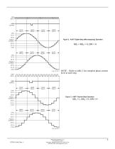
STEP INPUT HOME OUTPUT SLOW DECAY MIXED DECAY SLOW DECAY MIXED DECAY Figure 2. A3977 Eighth-Step (Microstepping) Operation MIXED DECAY SLOW DECAY MIXED DECAY SLOW DECAY STEP INPUT NOTE – Refer to table 2 for complete phase current level at each step. HOME OUTPUT SLOW DECAY MIXED DECAY SLOW DECAY MIXED DECAY Figure 3. A3977 Quarter-Step Operation MIXED DECAY SLOW DECAY MIXED DECAY SLOW DECAY Allegro MicroSystems, LLC 115 Northeast Cutoff Worcester, Massachusetts 01615-0036 U.S.A. 1.508.853.5000; www.allegromicro.com
Open the catalog to page 5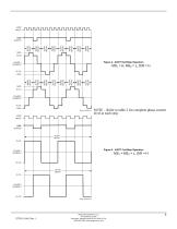
STEP INPUT MIXED DECAY SLOW DECAY MIXED DECAY SLOW DECAY MIXED DECAY SLOW DECAY MIXED DECAY SLOW DECAY HOME OUTPUT Figure 4. A3977 Half-Step Operation SLOW DECAY MIXED DECAY SLOW DECAY MIXED DECAY SLOW DECAY MIXED DECAY SLOW DECAY MIXED DECAY NOTE – Refer to table 2 for complete phase current level at each step. STEP INPUT HOME OUTPUT SLOW DECAY Figure 5. A3977 Full-Step Operation SLOW DECAY Allegro MicroSystems, LLC 115 Northeast Cutoff Worcester, Massachusetts 01615-0036 U.S.A. 1.508.853.5000; www.allegromicro.com
Open the catalog to page 6All ALLEGRO MICROSYSTEMS catalogs and technical brochures
 A1340
A134042 Pages
 A1324
A132412 Pages
 A1318
A131812 Pages
 A1308
A130812 Pages
 A1304
A130410 Pages
 A1367
A136727 Pages
 A1366
A136622 Pages
 A1365
A136532 Pages
 ACS770
29 Pages
 ACS758
22 Pages
 ACS761
14 Pages
 A1301 and A1302
10 Pages
 ACS709
17 Pages
 ACS716
22 Pages
 ACS715
14 Pages
 ACS714
18 Pages
 ACS712
15 Pages
 ACS713
14 Pages
 ACS756
11 Pages
 ACS710
23 Pages
 ACS711
16 Pages
 A1360, A1361, and A1362
26 Pages
 ACS759
19 Pages
 Advances in WLED/RGB LED Drivers
13 Pages


Archived catalogs
 A6261: Protected LED Array Driver
14 Pages
 Current Sensors
9 Pages


- Lumibird single-pole switch
- Lumibird proximity sensor
- Lumibird technology switch
- Position transducer
- Lumibird multipole switch
- Motor controller
- Linear position transmitter
- Analog position transducer
- No-contact position sensor
- Stepper motor controller
- Magnetic position sensor
- Bipolar switch
- Industrial position sensor
- Magnetic proximity sensor
- Lumibird speed controller
- Magnetic speed sensor
- Angular position sensor
- Rotational speed sensor
- Precision position sensor