- Catalogs
- ALLEGRO MICROSYSTEMS
- Current Sensors
Current Sensors
1 /9Pages

Current Sensors
1 /9Pages
Catalog excerpts

Bus BarPCB Trace I I > Tot I > Tot I > Sens I > Sens I > Shunt I > Shunt I I > Sens Sens Tot I > Tot
Open the catalog to page 1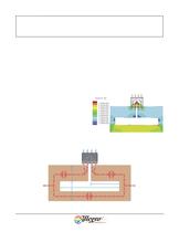
Figure 3. Simulated Current Density for > 1 / > 3 I > Tot Measurement. Data taken at 45 A I > Tot , with 4-oz copper trace. > 5 mm3 mm8.5 mm18 mm3 mm Sense PathI > Tot AB ACS704PCB Trace Shunt PathI > Tot Figure 2. ACS704 PCB Trace Configurations for > 1 / > 3 I > Tot Measurement. The ACS704 is mounted to the PCB trace, in series along the current sense subpath (corresponding to I > PRIMARY through the current sensor). 2 > Worcester, Massachusetts 01615-0036 (508) 853-5000115 Northeast Cutoff, Box 15036 www.allegromicro.comAllegro MicroSystems, Inc. size="-3">
Open the catalog to page 2
I > Sens ֏ > c L > Shunt W > Sens R > Primary W Sens T + O > c ( L > Sens1 + L > Sens2 ) > Table 2: Calculated Effect of PCB Trace Weight on Power Dissipation Through Dual Package Divider Trace Weight (oz copper)Power Dissipation at 30 A (W)Overall Resistance(m 5 mm2.2 mm1.7 mmACS704 Packagewith Die ACS704 Packagewithout Die I TotPCB Trace I Tot 8 mm Primary Conduction Path Hall Element Figure 5. Dual Package Solution. Equally divides I Tot using an active and a dummy ACS704 package.Figure 6. Simulated Current Density for Dual Packages. Data taken at 30 A I Tot , with 4-oz copper trace. 4 Worcester,...
Open the catalog to page 4
Tot S ACS7xx(B) VCC 40 k R7-120 k > P VOUTGND (TYP)R7-220 k 80 k 2.5 V80 k 40 k V > S 40 k ResultSignal Add Outputs I 80 k (TYP)R820 k ACS7xx(A) VOUTGNDVCC V 80 k I > P 40 k (TYP)40 k 40 k SubtractOffset andAdjust Gain I Invert Signal A > Worcester, Massachusetts 01615-0036 (508) 853-5000115 Northeast Cutoff, Box 15036 www.allegromicro.comAllegro MicroSystems, Inc. size="-1">
Open the catalog to page 5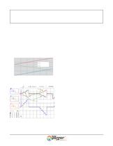
4321I ACS704 (A)ACS704 (B)Combined (V) OUT V 0051015202530 Tot (A) Figure 9. Simulation of Output. Results using ACS704 sen-sors in suggested circuit for combining outputs (figure 8). > Sensor B (red trace) Sensor A (black trace) Output (blue trace) Figure 10. Application of 30 A Pattern to I > Primary in 6 A Incre-ments. The lowest (blue) trace is the output of the interface circuit for combining the two ACS704 outputs. Note that the signals are dc-offset shifted on the oscilloscope, for viewing. 6 > Worcester, Massachusetts 01615-0036 (508) 853-5000115 Northeast Cutoff, Box 15036 www.allegromicro.comAllegro...
Open the catalog to page 6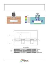
12 mm7.5 mm13 mm26.5 mm4.3 mm CopperBus Bar Sense PathI I > Tot AB ACS754 > Tot Shunt Path > Tot using an ACS754 sensor in series on a 1-mm-thick copper bus bar.Figure 12. Simulated Current Density for > 1 / > 2 I > Tot Measure-ment. Data taken at 300 A I > Tot , with 4-oz copper trace. Figure 13. Plan and Cross-Section Views of Multilayer Board. This approach, using ACS754 family devices, divides the current according to layer chracteristics, passing a controlled proportion of I > Tot through sensor A. Figure 11. Higher Current Solution. Equally divides I 7 > Worcester, Massachusetts 01615-0036...
Open the catalog to page 7
AB CopperBus Bar I > Tot 25 mm25 mm I > Tot Figure 14. Higher Current Solution. Equally divides I > Tot using an ACS754 sensor in series.Figure 15. Simulated Current Density for > 1 / > 2 I > Tot Measure-ment. Data taken at 300 A I > TOT , with 4-oz copper trace. 8 > Worcester, Massachusetts 01615-0036 (508) 853-5000115 Northeast Cutoff, Box 15036 www.allegromicro.comAllegro MicroSystems, Inc. size="-3">
Open the catalog to page 8All ALLEGRO MICROSYSTEMS catalogs and technical brochures
 A1340
A134042 Pages
 A1324
A132412 Pages
 A1318
A131812 Pages
 A1308
A130812 Pages
 A1304
A130410 Pages
 A1367
A136727 Pages
 A1366
A136622 Pages
 A1365
A136532 Pages
 ACS770
29 Pages
 ACS758
22 Pages
 ACS761
14 Pages
 A1301 and A1302
10 Pages
 ACS709
17 Pages
 ACS716
22 Pages
 ACS715
14 Pages
 ACS714
18 Pages
 ACS712
15 Pages
 ACS713
14 Pages
 ACS756
11 Pages
 ACS710
23 Pages
 ACS711
16 Pages
 A1360, A1361, and A1362
26 Pages
 ACS759
19 Pages
 Advances in WLED/RGB LED Drivers
13 Pages


Archived catalogs
 A6261: Protected LED Array Driver
14 Pages


- Lumibird single-pole switch
- Lumibird proximity sensor
- Lumibird technology switch
- Position transducer
- Lumibird multipole switch
- Motor controller
- Linear position transmitter
- Analog position transducer
- No-contact position sensor
- Stepper motor controller
- Magnetic position sensor
- Bipolar switch
- Industrial position sensor
- Magnetic proximity sensor
- Lumibird speed controller
- Magnetic speed sensor
- Angular position sensor
- Rotational speed sensor
- Motor driver
- Precision position sensor