- Catalogs
- ALLEGRO MICROSYSTEMS
- A6261: Protected LED Array Driver
A6261: Protected LED Array Driver
1 /14Pages

A6261: Protected LED Array Driver
1 /14Pages
Catalog excerpts
Description The A6261 is a linear, programmable current regulator providing up to 100 mA from each of four outputs to drive arrays of high brightness LEDs. The regulated LED current from each output, accurate to 5%, is set by a single reference resistor. Current matching in each string is better than 10% without the use of ballast resistors. Driving LEDs with constant current ensures safe operation with maximum possible light output. Output control is provided by an enable input, giving direct control for PWM applications. Outputs can be connected in parallel or left unused as required. Short detection is provided to protect the LEDs and the A6261 during a short-to-ground at any LED output pin. An open LED in any of the strings disables all outputs, but can be overridden. Shorted LED output pins or open LEDs are indicated by a fault flag. A temperature monitor is included to reduce the LED drive current if the chip temperature exceeds a thermal threshold. The device packages are a 10-pin MSOP (LY) and a 16-pin TSSOP (LP), both with exposed pad for enhanced thermal dissipation. They are lead (Pb) free, with 100% matte tin leadframe plating. A6261A-DS, Rev. 3 Features and Benefits Total LED drive current up to 400 mA Current shared equally up to 100 mA by up to 4 strings 6 to 50 V supply Low dropout voltage LED output short-to-ground and thermal protection Disable on open LED detection option Enable input for PWM control Current slew rate limit during PWM Current set by reference resistor Automotive K-temperature range version (–40°C to 150°C) Packages Typical Application Diagram Not to scale A6261 Protected LED Array Driver A6261 + – LA1 VIN PWM dimming input Power input GND LA2 LA3 LA4 EN FF IREF THTH 10-pin MSOP with exposed thermal pad (suffix LY) 16-pin TSSOP with exposed thermal pad (suffix LP)
Open the catalog to page 1
A6261 Protected LED Array Driver Allegro MicroSystems, Inc. 2 115 Northeast Cutoff Worcester, Massachusetts 01615-0036 U.S.A. 1.508.853.5000; www.allegromicro.com Absolute Maximum Ratings1 Characteristic Symbol Notes Rating Unit Load Supply Voltage VIN –0.3 to 50 V Pin EN –0.3 to 50 V Pins LA[1:4] –0.3 to 50 V Pin FF –0.3 to 50 V Pins IREF, THTH –0.3 to 6.5 V Ambient Operating Temperature Range2 TA E temperature range –40 to 85 °C K temperature range –40 to 125 °C Maximum Continuous Junction Temperature TJ(max) 150 °C Transient Junction Temperature TtJ Over temperature event not exceeding 10...
Open the catalog to page 2
A6261 Protected LED Array Driver Allegro MicroSystems, Inc. 3 115 Northeast Cutoff Worcester, Massachusetts 01615-0036 U.S.A. 1.508.853.5000; www.allegromicro.com Pin-out Diagrams LP Package LY Package LA1 VIN +V Current Regulators GND PAD Fault Control Temp Comp Temp Monitor Slew Limit Current Reference Control Logic LA2 LA3 LA4 EN FF IREF RREF RTH THTH Functional Block Diagram THTH IREF GND LA1 LA2 FF EN VIN LA4 LA3 1 2 3 4 5 10 9 8 7 6 PAD NC NC THTH IREF GND LA1 LA2 NC NC NC FF EN VIN LA4 LA3 NC 1 2 3 4 5 6 7 8 16 15 14 13 12 11 10 9 PAD Terminal List Table Name Number LP LY Function EN 13...
Open the catalog to page 3
A6261 Protected LED Array Driver Allegro MicroSystems, Inc. 4 115 Northeast Cutoff Worcester, Massachusetts 01615-0036 U.S.A. 1.508.853.5000; www.allegromicro.com Supply and Reference VIN Functional Operating Range2 6 – 50 V VIN Quiescent Current IINQ LA[1:4] connected to VIN – – 10 mA VIN Sleep Current IINS EN = GND – – 10 ìA Startup Time tON VIN > 7 V to ILA1 < –5 mA, RREF = 125 Ù 5 20 30 ìs Current Regulation Reference Voltage VIREF 0.7 mA < IREF < 8.8 mA 1.15 1.2 1.25 V Reference Current Ratio GH ILAx / IREF – 12.5 – – Current Accuracy3 EILAx –10 mA > ILAx > –100 mA –5 ±4 5 % Current Matching4...
Open the catalog to page 4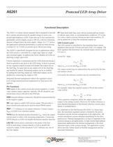
A6261 Protected LED Array Driver Allegro MicroSystems, Inc. 5 115 Northeast Cutoff Worcester, Massachusetts 01615-0036 U.S.A. 1.508.853.5000; www.allegromicro.com Functional Description The A6261 is a linear current regulator that is designed to provide drive current and protection for parallel strings of series-connected high brightness LEDs. It provides up to four matched programmable current outputs, at up to 100 mA, with low minimum dropout voltages below the main supply voltage. For 12 V power net applications optimum performance is achieved when driving 4 strings of 1 to 3 LEDs, at currents...
Open the catalog to page 5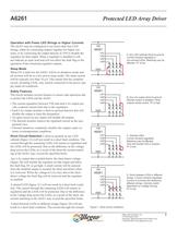
A6261 Protected LED Array Driver Allegro MicroSystems, Inc. 6 115 Northeast Cutoff Worcester, Massachusetts 01615-0036 U.S.A. 1.508.853.5000; www.allegromicro.com Operation with Fewer LED Strings or Higher Currents The A6261 may be configured to use fewer than four LED strings, either by connecting outputs together for higher currents, or by connecting the output directly to VIN to disable the regulator for that output. When a regulator is disabled it will not indicate an open load and will not affect the fault flag or the operation of the remaining regulator outputs. Sleep Mode When EN is held...
Open the catalog to page 6
A6261 Protected LED Array Driver Allegro MicroSystems, Inc. 7 115 Northeast Cutoff Worcester, Massachusetts 01615-0036 U.S.A. 1.508.853.5000; www.allegromicro.com ing LEDs will remain in regulation and the LEDs will be protected. The current will be summed and shared by the affected strings. Current matching in the strings will then depend on the LED forward voltage differences. Open Load Detection An open load condition is detected when the voltage across the regulator, VIN – VLAx , is less than the open load detect voltage, VOCD , but greater than the output disable threshold voltage, VODIS...
Open the catalog to page 7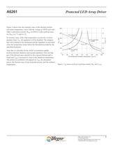
A6261 Protected LED Array Driver Allegro MicroSystems, Inc. 8 115 Northeast Cutoff Worcester, Massachusetts 01615-0036 U.S.A. 1.508.853.5000; www.allegromicro.com Figure 3 shows how the nominal value of the thermal monitor activation temperature varies with the voltage at THTH and with either a pull-down resistor, RTH, to GND or with a pull-up resistor, RTH , to 3 V and to 5 V. In extreme cases, if the chip temperature exceeds the overtemperature limit, TJF , all regulators will be disabled. The temperature will continue to be monitored and the regulators re-activated when the temperature drops...
Open the catalog to page 8All ALLEGRO MICROSYSTEMS catalogs and technical brochures
 A1340
A134042 Pages
 A1324
A132412 Pages
 A1318
A131812 Pages
 A1308
A130812 Pages
 A1304
A130410 Pages
 A1367
A136727 Pages
 A1366
A136622 Pages
 A1365
A136532 Pages
 ACS770
29 Pages
 ACS758
22 Pages
 ACS761
14 Pages
 A1301 and A1302
10 Pages
 ACS709
17 Pages
 ACS716
22 Pages
 ACS715
14 Pages
 ACS714
18 Pages
 ACS712
15 Pages
 ACS713
14 Pages
 ACS756
11 Pages
 ACS710
23 Pages
 ACS711
16 Pages
 A1360, A1361, and A1362
26 Pages
 ACS759
19 Pages
 Advances in WLED/RGB LED Drivers
13 Pages


Archived catalogs
 Current Sensors
9 Pages


- Lumibird single-pole switch
- Lumibird proximity sensor
- Lumibird technology switch
- Position transducer
- Lumibird multipole switch
- Motor controller
- Linear position transmitter
- Analog position transducer
- No-contact position sensor
- Stepper motor controller
- Magnetic position sensor
- Bipolar switch
- Industrial position sensor
- Magnetic proximity sensor
- Lumibird speed controller
- Magnetic speed sensor
- Angular position sensor
- Rotational speed sensor
- Motor driver
- Precision position sensor