
- Catalogs
- ALLEGRO MICROSYSTEMS
- A5303: Photoelectric Smoke Detector with Interconnect, Timer, and Latching Alarm Indicator

- Products
- Catalogs
- News & Trends
- Exhibitions
A5303: Photoelectric Smoke Detector with Interconnect, Timer, and Latching Alarm Indicator

A5303: Photoelectric Smoke Detector with Interconnect, Timer, and Latching Alarm Indicator
- HORN Pin: Activates the boost converter to sound the piezo horn. If not used, leave open.
- BLINK Pin: Controls LED blinking in standby mode. Connected to VDD for blinking every 43 seconds; connected to VSS for no blinking.
- LED Pin: Drives a visible LED to indicate detector status, with different pulse occurrences for various conditions.
- OSC CAP Pin: Works with a capacitor and resistor to set the internal clock low time, affecting the STROBE pulse width.
- TRES Pin: Sets the internal clock high time, affecting the IRED pulse width.
- VSS Pin: Connects to the negative supply potential, usually ground.
- HUSH Pin: Enables/disables the 10-minute hush timer mode and serves as a reference for the smoke comparator during this mode.
- TEST Pin: Used to manually invoke test modes and reset the latching alarm indicator.
- Standby Mode: The device can blink the LED based on the BLINK pin configuration.
- Timer (Hush) Mode: Temporarily reduces sensitivity to avoid nuisance alarms.
- Push-to-Test Mode: Simulates smoke conditions to test the detector's functionality.
- Diagnostic Test/Calibration Mode: Facilitates calibration and testing of the IC and detector.
- Latching Alarm Indicator: Identifies which detector initiated an alarm in a networked setup.
- Periodic Tests: Includes degraded-chamber and low-battery tests occurring every 45.9 minutes, with specific signals for failed tests.
Catalog excerpts
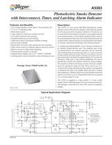
Description The A5303 is a low-current BiCMOS photoelectric smoke detector circuit with ultra-low standby current and can operate for 10 years powered by inexpensive batteries. This device can be used with an infrared optical chamber to sense light scattered from smoke particles. A networking capability allows units to be interconnected so that if any unit senses smoke all units will sound an alarm. Special features are incorporated in the design to facilitate calibration and testing of the finished detector. A variable-gain photoamplifier can be directly interfaced to an infrared emitter-detector pair. The amplifier gain levels are determined by two external capacitors and are internally selected depending on the operating mode. Low gain is selected during standby and timer modes. During a local alarm, this low gain is increased (internally) by approximately 45% to provide hysteresis. High gain is used during pushbutton test and to periodically monitor the chamber sensitivity during standby. The internal oscillator and timing circuitry minimize standby power by sensing for smoke for only 100 ìs once every 10 s. A special three-stage-speedup sensing scheme is incorporated to minimize the time to an audible alarm and also to reduce false triggering. Chamber sensitivity is periodically monitored and two consecutive cycles of degraded sensitivity are required for a warning signal to occur. The A5303 is supplied in a thin profile (<1.2 mm overall height) 20-pin TSSOP package (0.65 mm nominal lead pitch). The package is lead (Pb) free with 100% matte tin leadframe plating. 5303-DS Features and Benefits Low average standby current allows 10-year battery life 2.3 to 5.5 V operating range Interconnect option Logic outputs to control an external sound IC Low battery detection and warning Chamber sensitivity test and warning Triple horn-chirp to distinguish chamber warning Power-on reset (POR) Digital filter on I/O provides significant noise immunity Timer (hush) mode for enabling reduced sensitivity period Built-in circuits to reduce false triggering ESD protection circuitry on all pins Temporal Horn Pattern, per UL217, NFPA72, ISO8201 Latching alarm indicator identifies alarm-initiating devices Photoelectric Smoke Detector with Interconnect, Timer, and Latching Alarm Indicator Package: 20-pin TSSOP (suffix LE) Not to scale A5303 Typical Application Diagram Control Logic SOUT0 VDD TEST C1 56 nF C2 5.6 nF DETECT Gain Select STROBE VDD IRED OSC Timing Low Batt 1.2 V 3 V 100 ìF LED VSS 560 Ù 200 kÙ 10 ìF VDD - 1.6 V OSCCAP 1500 pf Push-to-test HUSH Connect HUSH to VSS to disable timer mode Connect to allow timer (hush) mode operation ISET LVSET Low Batt Sample A A A resistor connected between this pin and VDD or VSS adjusts SOUT1 Voice IC outputs the low-battery threshold 100 kÙ 10 ÌÙ SOUT2 TRES I/O 220 Ù To / from other units VDD VDD VDD BLINK In standby, BLINK = VDD causes LED to blink, BLINK = VSS causes LED not to blink HORN Output to optional boost converter to drive a piezo horn Smoke Chamber Red LED B B R1 R2 5 k Ù 3 kÙ 3 Ù 1 k Ù
Open the catalog to page 1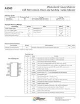
Photoelectric Smoke Detector A5303 with Interconnect, Timer, and Latching Alarm Indicator Allegro MicroSystems, Inc. 2 115 Northeast Cutoff Worcester, Massachusetts 01615-0036 U.S.A. 1.508.853.5000; www.allegromicro.com Selection Guide Part Number Pb-free and RoHS Package Packing A5303SLE-T Yes 20-pin TSSOP (JEDEC MO-153AC) 75 pieces / tube A5303SLETR-T Yes 20-pin TSSOP (JEDEC MO-153AC) 4000 pieces / reel Absolute Maximum Ratings Characteristic Symbol Notes Rating Units Supply Voltage Range VDD Referenced to VSS –2.3 to 6 V DC Input Voltage Range VIN Referenced to VSS –0.3 to 6 V Operating Ambient...
Open the catalog to page 2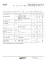
Photoelectric Smoke Detector A5303 with Interconnect, Timer, and Latching Alarm Indicator Allegro MicroSystems, Inc. 3 115 Northeast Cutoff Worcester, Massachusetts 01615-0036 U.S.A. 1.508.853.5000; www.allegromicro.com DC ELECTRICAL CHARACTERISTICS1 Valid at TA = 25°C, VDD = 2.3 to 5.5 V, configured as in Typical Application Diagram (unless otherwise noted) Characteristics Symbol Test Conditions Min. Typ.2 Max. Unit Supply Voltage Range VDD Operating 2.3 3.0 5.5 V Operating Supply Current IDD During standby, STROBE off – 2.3 5.0 ìA During STROBE on, IRED off – 210 300 ìA During STROBE on, IRED...
Open the catalog to page 3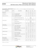
Photoelectric Smoke Detector A5303 with Interconnect, Timer, and Latching Alarm Indicator Allegro MicroSystems, Inc. 4 115 Northeast Cutoff Worcester, Massachusetts 01615-0036 U.S.A. 1.508.853.5000; www.allegromicro.com Continued on the next page… AC ELECTRICAL CHARACTERISTICS1 Valid at TA = 25°C, VDD = 2.3 to 5.5 V, configured as in Typical Application Diagram (unless otherwise noted) Characteristics Symbol Test Conditions OSC Count Min. Typ.2 Max. Unit Oscillator Period tosc 1 9.4 10.5 11.5 ms Smoke Check tsmoke 210 9.6 10.75 11.9 s Low Battery Test tbattery No low-battery detected 218 41.3...
Open the catalog to page 4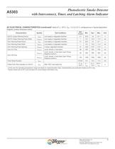
Photoelectric Smoke Detector A5303 with Interconnect, Timer, and Latching Alarm Indicator Allegro MicroSystems, Inc. 5 115 Northeast Cutoff Worcester, Massachusetts 01615-0036 U.S.A. 1.508.853.5000; www.allegromicro.com SOUTx Output Warning Period tsoutx Low supply or degraded chamber 212 38.9 43 47.1 s SOUTx Output Warning Pulse Width tw(soutx) Low supply or degraded chamber 1 9.5 10.5 11.5 ms Horn Warning Pulse Period thorn Low battery or degraded chamber 212 38.9 43 47.1 s Horn Warning Pulse Width tw(horn) Low battery or degraded chamber 1 9.5 10.5 11.5 ms Horn Warning Pulse Spacing tsp(horn)...
Open the catalog to page 5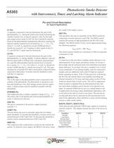
Photoelectric Smoke Detector A5303 with Interconnect, Timer, and Latching Alarm Indicator Allegro MicroSystems, Inc. 6 115 Northeast Cutoff Worcester, Massachusetts 01615-0036 U.S.A. 1.508.853.5000; www.allegromicro.com Pin and Circuit Description (In Typical Application) C1 Pin A capacitor connected to this pin determines the gain of the photoamplifier, Ae , during the push-to-test mode and during the chamber monitor test. A typical capacitor value for this highgain (supervisory) mode is 0.047 ìF, but it should be selected based on the photochamber background reflections reaching the detector...
Open the catalog to page 6All ALLEGRO MICROSYSTEMS catalogs and technical brochures
 A1340
A134042 Pages
 A1324
A132412 Pages
 A1318
A131812 Pages
 A1308
A130812 Pages
 A1304
A130410 Pages
 A1367
A136727 Pages
 A1366
A136622 Pages
 A1365
A136532 Pages
 ACS770
29 Pages
 ACS758
22 Pages
 ACS761
14 Pages
 A1301 and A1302
10 Pages
 ACS709
17 Pages
 ACS716
22 Pages
 ACS715
14 Pages
 ACS714
18 Pages
 ACS712
15 Pages
 ACS713
14 Pages
 ACS756
11 Pages
 ACS710
23 Pages
 ACS711
16 Pages
 A1360, A1361, and A1362
26 Pages
 ACS759
19 Pages
 Advances in WLED/RGB LED Drivers
13 Pages


Archived catalogs
 A6261: Protected LED Array Driver
14 Pages
 Current Sensors
9 Pages


- Proximity switch
- Single-pole switch
- Technology switch
- Position transducer
- Multipole switch
- Motor controller
- Linear position transmitter
- Analog position transducer
- No-contact position sensor
- Stepper motor controller
- Magnetic position sensor
- Bipolar switch
- Industrial position sensor
- Magnetic proximity sensor
- Motor driver
- Speed controller
- Angular position sensor
- Proximity sensor with switching function
- Magnetic speed sensor
- Rotational speed sensor