- Catalogs
- ALLEGRO MICROSYSTEMS
- A4402: Constant On-Time Buck Converter with Integrated Linear Regulator
A4402: Constant On-Time Buck Converter with Integrated Linear Regulator
1 /15Pages

A4402: Constant On-Time Buck Converter with Integrated Linear Regulator
1 /15Pages
Catalog excerpts
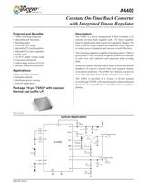
Description The A4402 is a power management IC that combines a 2% constant on-time buck regulator and a 2% linear regulator. Ideal for applications that require two regulated voltages. The buck regulator output supplies the adjustable linear regulator to reduce power dissipation and increase overall efficiency. The switching regulator is capable of operating above 2 MHz. A greater than 2 MHz switching frequency enables the customer to select low value inductors and capacitors while avoiding EMI. Protection features include undervoltage lockout and thermal shutdown. In case of a shorted load, each regulator features overcurrent protection. The A4402 also features a power-on reset with adjustable delay for the microprocessor output. The A4402 is provided in a 16-pin, 1.20 mm nominal overall height TSSOP, with exposed pad for enhanced thermal dissipation. It is lead (Pb) free, with 100% matte tin leadframe plating. 4402-DS, Rev. 2 Features and Benefits 2 MHz switching frequency Adjustable soft start timer Watchdog input Power-on reset output Adjustable 2% buck regulator Adjustable 2% linear regulator Enable input 6 to 50 V supply voltage range Overcurrent protection Undervoltage lockout (UVLO) Thermal shutdown protection Constant On-Time Buck Converter with Integrated Linear Regulator Package: 16-pin TSSOP with exposed thermal pad (suffix LP) Typical Application Not to scale A4402 ENB VO2 NPOR GND GND GND 1 ìF 3.3 V 300 mA VO2 L1 33 ìH VIN1 LX FB1 10 ìF VBAT FB2 VIN2 POR CPOR TSET CTSET 5 V 0.1 ìF ISEN VLIN VSW Switching Regulator Output Linear Regulator Output A4402 TON 0.01 ìF RSENSE 4.7 ìF 20 Rton 750 kÙ kÙ kÙ WDI 0.33 ìF 0.15 ìF kÙ R1 31.6 kÙ R2 9.76 R3 10 R4 5.62 kÙ 4.7 kÙ BOOT Photo and inkjet printers Industrial controls Distributed power systems Network applications Applications:
Open the catalog to page 1
Constant On-Time Buck Converter A4402 with Integrated Linear Regulator Allegro MicroSystems, Inc. 2 115 Northeast Cutoff Worcester, Massachusetts 01615-0036 U.S.A. 1.508.853.5000; www.allegromicro.com Pin-out Diagram Absolute Maximum Ratings Characteristic Symbol Notes Rating Units VIN1 Pin VIN1 –0.3 to 50 V VIN2 Pin VIN2 –0.3 to 7 V LX Pin VLX –1 to 50 V ISEN Pin VISEN –0.5 to 1 V ENB Pin VENB –0.3 to 7 V VO2 Pin VO2 –0.3 to 7 V WDI Pin VWDI –0.3 to 6 V TON Pin VTON –0.3 to 7 V FB1 and FB2 Pins VFBx –0.3 to 7 V NPOR VNPOR –0.3 to 6.5 V Ambient Operating Temperature TA Range E –40 to 85 °C Junction...
Open the catalog to page 2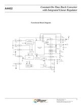
Constant On-Time Buck Converter A4402 with Integrated Linear Regulator Allegro MicroSystems, Inc. 3 115 Northeast Cutoff Worcester, Massachusetts 01615-0036 U.S.A. 1.508.853.5000; www.allegromicro.com Functional Block Diagram ENB VO2 NPOR VFB2 Internal Regulator VIN1 ENB 1 3.3 V 300 mA VO2 FAULT TSD L1 33 ìH LX FB1 BOOT Switch PWM Control Switch Disable Boot Charge 10 VBAT FB2 VIN2 POR CPOR Soft Start Ramp Generator Watchdog Timer TSET CTSET VREF VREF VREF VSW VLIN 5 V 0.1 ISEN VSW TON VREG VREG 0.01 4.7 20 VIN1 Rton 750 kÙ kÙ kÙ kÙ 4.7 kÙ kÙ kÙ WDI WDI 0.15 ìF 0.33 ìF R3 10 R4 5.62 R RSENSE...
Open the catalog to page 3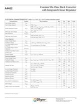
Constant On-Time Buck Converter A4402 with Integrated Linear Regulator Allegro MicroSystems, Inc. 4 115 Northeast Cutoff Worcester, Massachusetts 01615-0036 U.S.A. 1.508.853.5000; www.allegromicro.com Continued on the next page… ELECTRICAL CHARACTERISTICS1,2 valid at TJ = 25°C, VIN = 13.5 V (unless otherwise noted) Characteristics Symbol Test Conditions Min. Typ. Max. Units Input Voltage Supply 1 VIN1 6 13.5 50 V Input Voltage Supply 2 VIN2 VIN2 = VSW 3.3 – 5 V Supply Quiescent Current IIN(Q) ENB = 5 V, IOUT = ISW+ ILIN = 0 mA, VIN = 13.5 V – 10 – mA VIN1 = 13.5 V, ENB = 0 V, IOUT = ISW+ ILIN...
Open the catalog to page 4
Constant On-Time Buck Converter A4402 with Integrated Linear Regulator Allegro MicroSystems, Inc. 5 115 Northeast Cutoff Worcester, Massachusetts 01615-0036 U.S.A. 1.508.853.5000; www.allegromicro.com Protection Circuitry NPOR Output Voltage VNPOR INPOR = 1 mA – – 400 mV NPOR Leakage Current INPOR VNPOR = 5 V – – 1 ìA NPOR Reset VNPORRESET 20 kÙ pullup connected to VOUT2, VIN < – – 0.7 V Thermal Shutdown Threshold TJTSD TJ rising – 170 – ºC Thermal Shutdown Hysteresis TJTSDHYS – 15 – ºC Timing Circuitry TSET Current, Watchdog Mode ITSETWDI NPOR = high 7 10 14 ìA TSET Valley Voltage, Watchdog...
Open the catalog to page 5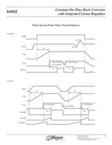
Constant On-Time Buck Converter A4402 with Integrated Linear Regulator Allegro MicroSystems, Inc. 6 115 Northeast Cutoff Worcester, Massachusetts 01615-0036 U.S.A. 1.508.853.5000; www.allegromicro.com VIN1 VIN1 ENB VSW VLIN NPOR UVLO Rising UVLO Rising tpor tss UVLO Falling UVLO Falling 6 V 18 V VSW VLIN NPOR tpor tss VPOR VCTSET UVLO Rising tpor UVLO Rising tpor tss Power-Up and Power-Down Timing Diagrams Using ENB Using VIN1
Open the catalog to page 6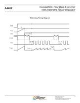
Constant On-Time Buck Converter A4402 with Integrated Linear Regulator Allegro MicroSystems, Inc. 7 115 Northeast Cutoff Worcester, Massachusetts 01615-0036 U.S.A. 1.508.853.5000; www.allegromicro.com Watchdog Timing Diagram ENB UVLO Rising Vreset Vtrip VSW NPOR tpor tss WDI VO2 VTSET twait tpor twait
Open the catalog to page 7
Constant On-Time Buck Converter A4402 with Integrated Linear Regulator Allegro MicroSystems, Inc. 8 115 Northeast Cutoff Worcester, Massachusetts 01615-0036 U.S.A. 1.508.853.5000; www.allegromicro.com Functional Description Basic Operation The A4402 contains a fixed on-time, adjustable voltage buck switching regulator with valley sensing current mode control, and an adjustable linear regulator designed to run off the buck regulator output. The constant on-time converter maintains a constant output frequency because the on-time is inversely proportional to the supply voltage. As the input voltage...
Open the catalog to page 8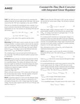
Constant On-Time Buck Converter A4402 with Integrated Linear Regulator Allegro MicroSystems, Inc. 9 115 Northeast Cutoff Worcester, Massachusetts 01615-0036 U.S.A. 1.508.853.5000; www.allegromicro.com TSET The TSET pin serves a dual function by controlling the timing for both the soft start ramp and the WDI input. The current sourced from the TSET pin is dependant on the state of NPOR. There are two formulas for calculating the time constants. CTSET must be selected so that both the WDI frequency and soft start requirements are met. The formulas for calculating WDI and soft start timing are:...
Open the catalog to page 9All ALLEGRO MICROSYSTEMS catalogs and technical brochures
 A1340
A134042 Pages
 A1324
A132412 Pages
 A1318
A131812 Pages
 A1308
A130812 Pages
 A1304
A130410 Pages
 A1367
A136727 Pages
 A1366
A136622 Pages
 A1365
A136532 Pages
 ACS770
29 Pages
 ACS758
22 Pages
 ACS761
14 Pages
 A1301 and A1302
10 Pages
 ACS709
17 Pages
 ACS716
22 Pages
 ACS715
14 Pages
 ACS714
18 Pages
 ACS712
15 Pages
 ACS713
14 Pages
 ACS756
11 Pages
 ACS710
23 Pages
 ACS711
16 Pages
 A1360, A1361, and A1362
26 Pages
 ACS759
19 Pages
 Advances in WLED/RGB LED Drivers
13 Pages


Archived catalogs
 A6261: Protected LED Array Driver
14 Pages
 Current Sensors
9 Pages


- Lumibird single-pole switch
- Lumibird proximity sensor
- Lumibird technology switch
- Lumibird position sensor
- Lumibird multipole switch
- Motor controller
- Lumibird linear position sensor
- Analog position transducer
- No-contact position sensor
- Stepper motor controller
- Lumibird magnetic position sensor
- Bipolar switch
- Industrial position sensor
- Magnetic proximity sensor
- Lumibird speed controller
- Magnetic speed sensor
- Angular position sensor
- Rotational speed sensor
- Motor driver
- Precision position sensor