
- Catalogs
- ALLEGRO MICROSYSTEMS
- A3930 and A3931: Automotive 3-Phase BLDC Controller and MOSFET Driver

- Products
- Catalogs
- News & Trends
- Exhibitions
A3930 and A3931: Automotive 3-Phase BLDC Controller and MOSFET Driver

A3930 and A3931: Automotive 3-Phase BLDC Controller and MOSFET Driver
The A3930 and A3931 are advanced 3-phase brushless DC (BLDC) motor controllers designed for automotive applications. They utilize N-channel external power MOSFETs and feature a charge pump regulator to ensure effective gate drive even at low battery voltages.
- High current 3-phase gate drive for N-channel MOSFETs
- Synchronous rectification and cross-conduction protection
- Charge pump for 100% PWM operation
- Integrated commutation decoder logic
- Operates over a 5.5 to 50 V supply voltage range
- Extensive diagnostics output and low-current sleep mode
The devices are housed in a 48-pin LQFP package with an exposed thermal pad, supporting a wide range of operating conditions:
- Load Supply Voltage: -0.3 to 50 V
- Operating Temperature Range: -40 to 150 °C
- ESD Ratings: 2000 V for most pins
Efficient motor control is achieved through:
- Fixed-frequency PWM current control
- Peak load current limit set by input reference voltage and external sensing resistor
- Efficiency enhancements via synchronous rectification
The A3930 and A3931 differ in their response to an all-zero Hall input state: the A3930 indicates a logic fault, while the A3931 pre-positions the motor for start-up algorithms.
These controllers are ideal for automotive 3-phase BLDC motor applications, offering robust performance and flexibility for various motor control strategies.
Effective heat dissipation is ensured through specified package thermal resistance for different PCB configurations.
The A3930 and A3931 provide a comprehensive solution for automotive BLDC motor control, combining high efficiency, extensive diagnostics, and robust protection features.
The document details the gate drive mechanism, including dead time introduction to prevent cross-conduction, and the use of external resistors to control FET gate charge and discharge rates. The A3931 includes an optional prepositioning function for motor start-up.
Various logic-level inputs are provided, such as RESET, COAST, MODE, DIR, BRAKE, and ESF, each serving specific functions like minimizing current consumption and determining motor direction.
The internal PWM control circuit regulates load current, with a differential current sense amplifier setting maximum current limits and the REF pin controlling torque.
Diagnostic features include speed and direction feedback through TACHO and DIRO outputs, and fault condition indications via FF1 and FF2 fault flags.
Emphasizes the importance of using appropriate resistor values, ensuring low-impedance connections, and handling fault conditions effectively with external circuits.
Logical AND operations determine fault states, with specific actions for faults like undervoltage and overtemperature, including disabling outputs or setting fault flags.
Proper capacitor placement is crucial for stable operation, with specified types and values for VBB, VREG, and V5 to ensure adequate power supply and transient current handling.
Selection and management of bootstrap capacitors are critical, with formulas provided for calculating appropriate values and ensuring correct charging.
Supports various motor control schemes, with internal PWM useful for torque control and external PWM for speed control, providing guidelines for setting PWM frequency to avoid audible noise.
Includes tables detailing input logic modes, commutation truth tables, and fault actions, providing quick reference for device operation under different conditions.
- Driving a Full-Bridge: Configuring Hall inputs and floating phase driver outputs as per the commutation truth table.
- Ground connections should minimize noise and ensure stable operation, with sensitive connections referenced to a quiet ground.
- Gate drive paths should be short to reduce inductance, and decoupling capacitors should be placed close to supply pins.
- Ensure CT and RDEAD values cover current spike durations and MOSFET gate capacitance variations.
- Monitor power MOSFET ratings during dynamic braking to prevent exceeding maximum limits.
Catalog excerpts
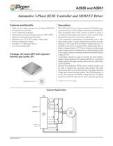
A3930 and A3931 Description The A3930 and A3931 are 3-phase brushless DC (BLDC) motor controllers for use with N-channel external power MOSFETs. They incorporate much of the circuitry required to design a cost effective three-phase motor drive system, and have been specifically designed for automotive applications. A key automotive requirement is functionality over a wide input supply range. A unique charge pump regulator provides adequate (>10 V) gate drive for battery voltages down to 7 V, and allows the device to operate with a reduced gate drive at battery voltages down to 5.5 V. Power dissipation in the charge pump is minimized by switching from a voltage doubling mode at low supply voltage to a dropout mode at the nominal running voltage of 14 V. A bootstrap capacitor is used to provide the above-battery supply voltage required for N-channel MOSFETs. An internal charge pump for the high-side drive allows for DC (100% duty cycle) operation. Internal fixed-frequency PWM current control circuitry can be used to regulate the maximum load current. The peak load current limit is set by the selection of an input reference voltage and external sensing resistor. The PWM frequency is set by a user-selected external RC timing network. For added flexibility, the PWM input can be used to provide speed and 3930-DS Rev. 4 Features and Benefits High current 3-phase gate drive for N-channel MOSFETs Synchronous rectification Cross-conduction protection Charge pump and top-off charge pump for 100% PWM Integrated commutation decoder logic Operation over 5.5 to 50 V supply voltage range Extensive diagnostics output Provides +5 V Hall sensor power Low-current sleep mode Automotive 3-Phase BLDC Controller and MOSFET Driver Typical Application Continued on the next page… Package: 48 Lead LQFP with exposed thermal pad (suffix JP) Approximate Scale 1:1
Open the catalog to page 1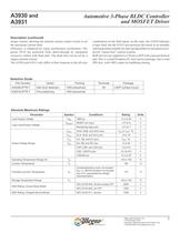
Automotive 3-Phase BLDC Controller and MOSFET Driver A3930 and A3931 Allegro MicroSystems, Inc. 2 115 Northeast Cutoff Worcester, Massachusetts 01615-0036 U.S.A. 1.508.853.5000; www.allegromicro.com torque control, allowing the internal current control circuit to set the maximum current limit. Efficiency is enhanced by using synchronous rectification. The power FETs are protected from shoot-through by integrated crossover control with dead time. The dead time can be set by a single external resistor. The A3930 and A3931 only differ in their response to the all-zero combination on the Hall inputs....
Open the catalog to page 2
Automotive 3-Phase BLDC Controller and MOSFET Driver A3930 and A3931 Allegro MicroSystems, Inc. 3 115 Northeast Cutoff Worcester, Massachusetts 01615-0036 U.S.A. 1.508.853.5000; www.allegromicro.com P High-Side Drive Low-Side Drive Blanking Charge Pump Regulator Charge Pump Boostrap Monitor +5V Ref OSC R S Q Diagnostics and Protection –UVLO –TSD –Short to Supply –Short to Ground –Shorted Winding –Low Load P RSENSE H1 H2 H3 V5 V5BD CA SA TACHO VBB RC RT CT RDEAD VDRAIN Phase A of three phases VDSTH REF CSOUT Control Logic LSS AGND CSN Pad CSP RESET TEST FF1 PWM FF2 GHA H1 V5 H2 H3 DIR DIRO GLA...
Open the catalog to page 3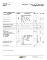
Automotive 3-Phase BLDC Controller and MOSFET Driver A3930 and A3931 Allegro MicroSystems, Inc. 4 115 Northeast Cutoff Worcester, Massachusetts 01615-0036 U.S.A. 1.508.853.5000; www.allegromicro.com ELECTRICAL CHARACTERISTICS at TJ = –40°C to 150°C, VBB = 7 to 45 V, unless otherwise noted1 Characteristics Symbol Test Conditions Min. Typ. Max. Units Supply and Reference VBB Functional Operating Range6 VBB Function correct, parameters not guaranteed 5.5 – 50 V VBB Quiescent Current IBBQ RESET = High, outputs = Low – 11 14 mA IBBS RESET = Low, sleep mode – – 10 ìA V5 Quiescent Current IV5Q RESET...
Open the catalog to page 4
Automotive 3-Phase BLDC Controller and MOSFET Driver A3930 and A3931 Allegro MicroSystems, Inc. 5 115 Northeast Cutoff Worcester, Massachusetts 01615-0036 U.S.A. 1.508.853.5000; www.allegromicro.com Continued on the next page… Turn-Off Propagation Delay tp(off) From Hall input change to unloaded gate output change 300 500 700 ns From other control input change to unloaded gate output change – 150 200 ns Dead Time (turn-off to turn-on delay) tDEAD RDEAD = 5 kÙƒn – 180 – ns RDEAD = 50 kÙ 835 960 1090 ns RDEAD = 400 kÙ – 3.3 – ìs RDEAD = tied to V5 – 6 – ìs Logic Inputs and Outputs FFx Fault Output...
Open the catalog to page 5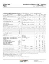
Automotive 3-Phase BLDC Controller and MOSFET Driver A3930 and A3931 Allegro MicroSystems, Inc. 6 115 Northeast Cutoff Worcester, Massachusetts 01615-0036 U.S.A. 1.508.853.5000; www.allegromicro.com Supply Rejection PSRR CSP = CSN = AGND, 0 to 300 kHz – 45 – dB Small Signal 3 dB Bandwidth Frequency f3dB VID=10 mVPP – 1.6 – MHz Settling Time tSETTLE To within 10%, VCSOUT = 1 VPP square wave – 400 – ns AC Common Mode Gain ACMac VICR= 250 mVPP, 0 to 1 MHz – –28 – dB Common Mode Recovery Time tCMrec To within 100 mV, VICR= +4.1 to 0 V step – 1 – ìs Output Slew Rate SR 10% to 90% points, VID= 0 to...
Open the catalog to page 6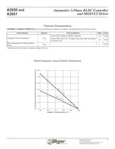
Automotive 3-Phase BLDC Controller and MOSFET Driver A3930 and A3931 Allegro MicroSystems, Inc. 7 115 Northeast Cutoff Worcester, Massachusetts 01615-0036 U.S.A. 1.508.853.5000; www.allegromicro.com Thermal Characteristics Power Dissipation versus Ambient Temperature THERMAL CHARACTERISTICS may require derating at maximum conditions, see Applications Information section Characteristic Symbol Test Conditions* Value Units Package Thermal Resistance RèJA 4-layer PCB, based on JEDEC standard 23 ºC/W 2-layer PCB, with 3 in.2 of copper area each side connected by thermal vias 44 ºC/W Die-to-Exposed...
Open the catalog to page 7
Automotive 3-Phase BLDC Controller and MOSFET Driver A3930 and A3931 Allegro MicroSystems, Inc. 8 115 Northeast Cutoff Worcester, Massachusetts 01615-0036 U.S.A. 1.508.853.5000; www.allegromicro.com Basic Operation The A3930 and A3931 devices provide commutation and current control for 3-phase brushless DC (BLDC) motors with integrated Hall-effect (HE) sensors. The motor current is provided by an external 3-phase N-channel MOSFET bridge which is controlled by the A3930/A3931, using fixed-frequency pulse width modulation (PWM). The use of PWM with N-channel MOSFETs provides the most cost-effective...
Open the catalog to page 8All ALLEGRO MICROSYSTEMS catalogs and technical brochures
 A1340
A134042 Pages
 A1324
A132412 Pages
 A1318
A131812 Pages
 A1308
A130812 Pages
 A1304
A130410 Pages
 A1367
A136727 Pages
 A1366
A136622 Pages
 A1365
A136532 Pages
 ACS770
29 Pages
 ACS758
22 Pages
 ACS761
14 Pages
 A1301 and A1302
10 Pages
 ACS709
17 Pages
 ACS716
22 Pages
 ACS715
14 Pages
 ACS714
18 Pages
 ACS712
15 Pages
 ACS713
14 Pages
 ACS756
11 Pages
 ACS710
23 Pages
 ACS711
16 Pages
 A1360, A1361, and A1362
26 Pages
 ACS759
19 Pages
 Advances in WLED/RGB LED Drivers
13 Pages


Archived catalogs
 A6261: Protected LED Array Driver
14 Pages
 Current Sensors
9 Pages


- Proximity switch
- Single-pole switch
- Technology switch
- Position transducer
- Multipole switch
- Linear position transmitter
- Analog position transducer
- No-contact position sensor
- Stepper motor controller
- Magnetic position sensor
- Bipolar switch
- Industrial position sensor
- Magnetic proximity sensor
- Motor driver
- Speed controller
- Angular position sensor
- Proximity sensor with switching function
- Magnetic speed sensor
- Rotational speed sensor