
- Catalogs
- ALLEGRO MICROSYSTEMS
- A1360, A1361, and A1362

- Products
- Catalogs
- News & Trends
- Exhibitions
A1360, A1361, and A1362

A1360, A1361, and A1362
Catalog excerpts
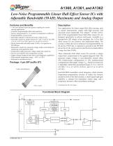
A1360, A1361, and A1362 Low-Noise Programmable Linear Hall Effect Sensor ICs with Adjustable Bandwidth (50 kHz Maximum) and Analog Output Features and Benefits • mm case thickness provides greater coupling for current 1 sensing applications • Customer programmable offset and sensitivity • Factory programmed 0% / °C sensitivity temperature coefficient • Programmability at end-of-line • Selectable unipolar or bipolar quiescent voltage levels • Selectable sensitivity ranges between 0.7 and 1.4 mV/G (A1360), 1.4 to 4.5 mV/G (A1361) and 4.5 to 16 mV/G (A1362) • Device bandwidth selectable under 50 kHz, via capacitor on FILTER pin • Ratiometric sensitivity, quiescent voltage output, and clamps for interfacing with application DAC • Temperature-stable quiescent voltage output and sensitivity • Precise recoverability after temperature cycling • Output voltage clamps provide short circuit diagnostic capabilities • Wide ambient temperature range: – 40°C to 150°C • Resistant to mechanical stress New applications for linear output Hall effect sensing, such as current measurement, require both high accuracy and increased sensor bandwidth. The Allegro™ A1360, A1361, and A1362 programmable linear Hall effect sensor ICs are designed specifically to achieve both goals. Available in a through-hole SIP (single in-line package), the A136x Hall effect sensor ICs are sensitive and temperature-stable. The accuracy of these devices is enhanced via programmability on the device VOUT pin. A capacitor to ground on the FILTER pin on the A136x can be used to tune the device bandwidth in a range less than 50 kHz. These ratiometric Hall effect sensor ICs provide a voltage output that is proportional to the applied magnetic field. The quiescent output voltage is user-adjustable around either 50% (bidirectional configuration) or 10% (unidirectional configuration) of the supply voltage, VCC. The device sensitivity is adjustable within three guaranteed ranges: 0.7 to 1.4 mV/G (A1360), 1.4 to 4.5 mV/G (A1361), and 4.5 to 16 mV/G (A1362). Package: 4 pin SIP (suffix KT) 1 mm case thickness Each BiCMOS monolithic circuit integrates a Hall element, temperature-compensation circuitry to reduce the intrinsic sensitivity drift of the Hall element, a small-signal high-gain amplifier, a clamped low-impedance output stage, and a proprietary dynamic offset cancellation technique. Continued on the next page… Functional Block Diagram V+ To subcircuits Ratiometric Hall Drive Program/Lock Trim Control Sensitivity Temperature Coefficient Signal Recovery Dynamic Offset Cancellation VOUT (Programming)
Open the catalog to page 1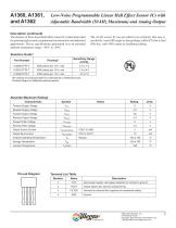
Low-Noise Programmable Linear Hall Effect Sensor ICs with Adjustable Bandwidth (50 kHz Maximum) and Analog Output Description (continued) The features of these linear Hall effect sensor ICs make them ideal for meeting high accuracy requirements in automotive and industrial applications. Device specifications guaranteed over an extended ambient temperature range: –40°C to 150°C. The A136x sensor ICs are provided in an extremely thin case (1 mm thick), 4-pin SIP (single in-line package, suffix KT) that is lead (Pb) free, with 100% matte tin leadframe plating. Selection Guide1 Sensitivity Range...
Open the catalog to page 2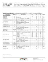
Low-Noise Programmable Linear Hall Effect Sensor ICs with Adjustable Bandwidth (50 kHz Maximum) and Analog Output OPERATING CHARACTERISTICS valid over full operating temperature range, TA; CBYPASS = 0.1 μF, VCC = 5 V, unless otherwise specied Characteristic Electrical Characteristics Supply Voltage Supply Current Supply Zener Clamp Voltage Internal Bandwidth Filtered Bandwidth Chopping Frequency2 Output Characteristics tRESPONSE tCLP VCLP(HIGH) Output Voltage Clamp3 VCLP(LOW) DC Output Resistance Output Load Resistance Output Load Capacitance Phase Shift5 Output Slew Rate6 Test Conditions No...
Open the catalog to page 3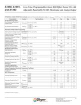
Low-Noise Programmable Linear Hall Effect Sensor ICs with Adjustable Bandwidth (50 kHz Maximum) and Analog Output OPERATING CHARACTERISTICS (continued) valid over full operating temperature range, TA; CBYPASS = 0.1 μF, VCC = 5 V, unless otherwise specied Characteristic Pre-Programming Target7 Pre-Programming Quiescent Voltage Output Pre-Programming Sensitivity VCLP(LOW) VOUT(Q)PRE Quiescent Voltage Output Programming VOUT(Q)UNIinit Initial Quiescent Voltage Output8 VOUT(Q)BIinit Coarse Quiescent Voltage Output Programming Bits9 VOUT(Q)UNI Guaranteed Quiescent Voltage Output Range10,11 VOUT(Q)BI...
Open the catalog to page 4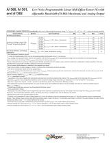
Low-Noise Programmable Linear Hall Effect Sensor ICs with Adjustable Bandwidth (50 kHz Maximum) and Analog Output OPERATING CHARACTERISTICS (continued) valid over full operating temperature range, TA; CBYPASS = 0.1 μF, VCC = 5 V, unless otherwise specied Characteristic Drift Characteristics Test Conditions A1360 Quiescent Voltage Output Drift Through Temperature Range1 Sensitivity Drift Due to Package Hysteresis1 A1361 VOUT(Q) = 2.5 V; Sens = Sens(min) A1360 A1361 VOUT(Q) = 2.5 V; Sens = Sens(max) A1362 TA = 25°C, after temperature cycling See Characteristic Definitions section. fC varies up...
Open the catalog to page 5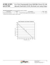
Low-Noise Programmable Linear Hall Effect Sensor ICs with Adjustable Bandwidth (50 kHz Maximum) and Analog Output Thermal Characteristics may require derating at maximum conditions Characteristic Package Thermal Resistance Test Conditions* 1-layer PCB with copper limited to solder pads *Additional thermal information available on Allegro website. Power Dissipation versus Ambient Temperature 900 800 Allegro MicroSystems, LLC 115 Northeast Cutoff Worcester, Massachusetts 01615-0036 U.S.A. 1.508.853.5000; www.allegromicro.com
Open the catalog to page 6
Low-Noise Programmable Linear Hall Effect Sensor ICs with Adjustable Bandwidth (50 kHz Maximum) and Analog Output Characteristic Data BW(max) 10 Guaranteed Range 1 10 100 1000 Capacitance External Capacitor on FILTER Pin, CF (nF) Step Response Sens = 2.2 mV/G Output (mV) 350 G Excitation Signal Allegro MicroSystems, LLC 115 Northeast Cutoff Worcester, Massachusetts 01615-0036 U.S.A. 1.508.853.5000; www.allegromicro.com
Open the catalog to page 7All ALLEGRO MICROSYSTEMS catalogs and technical brochures
 A1340
A134042 Pages
 A1324
A132412 Pages
 A1318
A131812 Pages
 A1308
A130812 Pages
 A1304
A130410 Pages
 A1367
A136727 Pages
 A1366
A136622 Pages
 A1365
A136532 Pages
 ACS770
29 Pages
 ACS758
22 Pages
 ACS761
14 Pages
 A1301 and A1302
10 Pages
 ACS709
17 Pages
 ACS716
22 Pages
 ACS715
14 Pages
 ACS714
18 Pages
 ACS712
15 Pages
 ACS713
14 Pages
 ACS756
11 Pages
 ACS710
23 Pages
 ACS711
16 Pages
 ACS759
19 Pages
 Advances in WLED/RGB LED Drivers
13 Pages


Archived catalogs
 A6261: Protected LED Array Driver
14 Pages
 Current Sensors
9 Pages


- Proximity switch
- Single-pole switch
- Technology switch
- Position transducer
- Multipole switch
- Motor controller
- Linear position transmitter
- Analog position transducer
- No-contact position sensor
- Stepper motor controller
- Magnetic position sensor
- Bipolar switch
- Industrial position sensor
- Magnetic proximity sensor
- Motor driver
- Speed controller
- Angular position sensor
- Proximity sensor with switching function
- Magnetic speed sensor
- Rotational speed sensor