- Catalogs
- ALLEGRO MICROSYSTEMS
- A1301 and A1302
A1301 and A1302
1 /10Pages

A1301 and A1302
1 /10Pages
Catalog excerpts
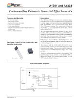
A1301 and A1302 Continuous-Time Ratiometric Linear Hall Effect Sensor ICs Features and Benefits The A1301 and A1302 are continuous-time, ratiometric, linear Hall-effect sensor ICs. They are optimized to accurately provide a voltage output that is proportional to an applied magnetic field. These devices have a quiescent output voltage that is 50% of the supply voltage. Two output sensitivity options are provided: 2.5 mV/G typical for the A1301, and 1.3 mV/G typical for the A1302. Low-noise output Fast power-on time Ratiometric rail-to-rail output 4.5 to 6.0 V operation Solid-state reliability Factory-programmed at end-of-line for optimum performance ▪ Robust ESD performance The Hall-effect integrated circuit included in each device includes a Hall circuit, a linear amplifier, and a CMOS Class A output structure. Integrating the Hall circuit and the amplifier on a single chip minimizes many of the problems normally associated with low voltage level analog signals. High precision in output levels is obtained by internal gain and offset trim adjustments made at end-of-line during the manufacturing process. Packages: 3-pin SOT23W (suffix LH), and 3-pin SIP (suffix UA) These features make the A1301 and A1302 ideal for use in position sensing systems, for both linear target motion and rotational target motion. They are well-suited for industrial applications over extended temperature ranges, from –40°C to 125°C. Two device package types are available: LH, a 3-pin SOT23W type for surface mount, and UA, a 3-pin ultramini SIP for through-hole mount. They are lead (Pb) free (suffix, –T) with 100% matte tin plated leadframes. Functional Block Diagram V+ CBYPASS Trim Control
Open the catalog to page 1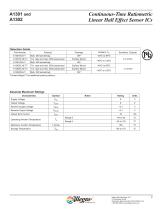
Continuous-Time Ratiometric Linear Hall Effect Sensor ICs Selection Guide Part Number 7-in. tape and reel, 3000 pieces/reel 7-in. tape and reel, 3000 pieces/reel Surface Mount 7-in. tape and reel, 3000 pieces/reel Surface Mount *Contact Allegro™ for additional packing options. Absolute Maximum Ratings Characteristic Supply Voltage Output Voltage Reverse Supply Voltage Reverse Output Voltage Output Sink Current Operating Ambient Temperature Maximum Junction Temperature Storage Temperature Allegro MicroSystems, LLC 115 Northeast Cutoff Worcester, Massachusetts 01615-0036 U.S.A. 1.508.853.5000;...
Open the catalog to page 2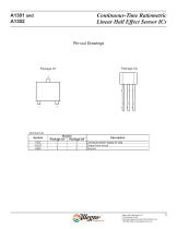
Continuous-Time Ratiometric Linear Hall Effect Sensor ICs Pin-out Drawings Terminal List Symbol VCC VOUT GND Description Connects power supply to chip Output from circuit Ground Allegro MicroSystems, LLC 115 Northeast Cutoff Worcester, Massachusetts 01615-0036 U.S.A. 1.508.853.5000; www.allegromicro.com
Open the catalog to page 3
Continuous-Time Ratiometric Linear Hall Effect Sensor ICs DEVICE CHARACTERISTICS over operating temperature range, TA, and VCC = 5 V, unless otherwise noted Characteristic Symbol Test Conditions Min. Electrical Characteristics Running, TJ < 165°C 4.5 Supply Voltage VCC Supply Current ICC Output open – VOUT(High) ISOURCE = –1 mA, Sens = nominal 4.65 Output Voltage – VOUT(Low) ISINK = 1 mA, Sens = nominal Output Bandwidth BW – VCC(min) to 0.95 VOUT; B = ±1400 G; Power-On Time tPO – Slew rate = 4.5 V/μs to 4.5 V/100 ns Output Resistance ROUT ISINK ≤ 1 mA, ISOURCE ≥ –1 mA – External output low pass...
Open the catalog to page 4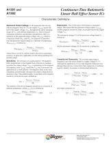
Continuous-Time Ratiometric Linear Hall Effect Sensor ICs Characteristic Definitions Quiescent Output Voltage. In the quiescent state (no significant magnetic field: B = 0), the output, VOUTQ, equals one half of the supply voltage, VCC, throughout the entire operating ranges of VCC and ambient temperature, TA. Due to internal component tolerances and thermal considerations, there is a tolerance on the quiescent output voltage, ∆VOUTQ, which is a function of both ∆VCC and ∆TA. For purposes of specification, the quiescent output voltage as a function of temperature, ∆VOUTQ(∆TA), is defined as:...
Open the catalog to page 5
Continuous-Time Ratiometric Linear Hall Effect Sensor ICs Typical Characteristics (30 pieces, 3 fabrication lots) 1301 Device Sensitivity vs. Ambient Temperature 1302 Device Sensitivity vs. Temperature 1.40 1301 Device VOUTQ vs. Ambient Temperature 1302 Device VOUTQ vs. Ambient Temperature 1301 Device Sensitivity vs. Supply Voltage 1302 Device Sensitivity vs. Supply Voltage 1.7 Continued on the next page... Allegro MicroSystems, LLC 115 Northeast Cutoff Worcester, Massachusetts 01615-0036 U.S.A. 1.508.853.5000; www.allegromicro.com
Open the catalog to page 6
Continuous-Time Ratiometric Linear Hall Effect Sensor ICs Typical Characteristics, continued (30 pieces, 3 fabrication lots) 1302 Device VOUTQ vs. Supply Voltage 1301 Device VOUTQ vs. Supply Voltage 3.5 Output Voltage (V) 1302 Device LIN+ and LIN– vs. Supply Voltage 1301 Device LIN+ and LIN– vs. Supply Voltage 100.4 1302 Device Symmetry vs. Supply Voltage 1301 Device Symmetry vs. Supply Voltage 100.5 Allegro MicroSystems, LLC 115 Northeast Cutoff Worcester, Massachusetts 01615-0036 U.S.A. 1.508.853.5000; www.allegromicro.com
Open the catalog to page 7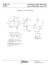
Continuous-Time Ratiometric Linear Hall Effect Sensor ICs 0.95 Seating Plane Gauge Plane PCB Layout Reference View Branded Face For Reference Only; not for tooling use (reference dwg. 802840) Dimensions in millimeters Dimensions exclusive of mold flash, gate burrs, and dambar protrusions Exact case and lead configuration at supplier discretion within limits shown A Standard Branding Reference View N = Last two digits of device part number T = Temperature code Active Area Depth, 0.28 mm REF Reference land pattern layout All pads a minimum of 0.20 mm from all adjacent pads; adjust as necessary...
Open the catalog to page 8
Continuous-Time Ratiometric Linear Hall Effect Sensor ICs 10° Mold Ejector Pin Indent Branded Face D Standard Branding Reference View = Supplier emblem N = Last three digits of device part number For Reference Only; not for tooling use (reference DWG-9065) Dimensions in millimeters Dimensions exclusive of mold flash, gate burrs, and dambar protrusions Exact case and lead configuration at supplier discretion within limits shown +0.05 0.43 –0.07 A Dambar removal protrusion (6X) Gate and tie bar burr area Active Area Depth, 0.50 mm REF Branding scale and appearance at supplier discretion Hall element...
Open the catalog to page 9All ALLEGRO MICROSYSTEMS catalogs and technical brochures
 A1340
A134042 Pages
 A1324
A132412 Pages
 A1318
A131812 Pages
 A1308
A130812 Pages
 A1304
A130410 Pages
 A1367
A136727 Pages
 A1366
A136622 Pages
 A1365
A136532 Pages
 ACS770
29 Pages
 ACS758
22 Pages
 ACS761
14 Pages
 ACS709
17 Pages
 ACS716
22 Pages
 ACS715
14 Pages
 ACS714
18 Pages
 ACS712
15 Pages
 ACS713
14 Pages
 ACS756
11 Pages
 ACS710
23 Pages
 ACS711
16 Pages
 A1360, A1361, and A1362
26 Pages
 ACS759
19 Pages
 Advances in WLED/RGB LED Drivers
13 Pages


Archived catalogs
 A6261: Protected LED Array Driver
14 Pages
 Current Sensors
9 Pages


- Lumibird single-pole switch
- Lumibird proximity sensor
- Lumibird technology switch
- Lumibird position sensor
- Lumibird multipole switch
- Motor controller
- Lumibird linear position sensor
- Analog position transducer
- No-contact position sensor
- Stepper motor controller
- Lumibird magnetic position sensor
- Bipolar switch
- Industrial position sensor
- Magnetic proximity sensor
- Lumibird speed controller
- Magnetic speed sensor
- Angular position sensor
- Rotational speed sensor
- Motor driver
- Precision position sensor