
- Catalogs
- ALBRIGHT INTERNATIONAL
- SW225 Heavy Duty D.C. Contactors for Power Distribution Centres

SW225 Heavy Duty D.C. Contactors for Power Distribution Centres

SW225 Heavy Duty D.C. Contactors for Power Distribution Centres
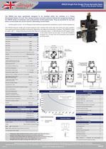
- Thermal Current Rating: 250A for interrupted, 350A for uninterrupted applications.
- Intermittent Current Rating: Varies with duty cycle, e.g., 410A at 30% duty.
- Rated Fault Current Breaking Capacity: 330A at 60V DC.
- Maximum Recommended Contact Voltage: 60V DC.
- Coil Voltage Available: 6 to 240V DC.
- Operating Temperature: -40°C to +60°C.
- Single pole, single throw, normally open configuration.
- Silver alloy contact tips for durability and conductivity.
- Horizontal or vertical mounting options with standard "L" shape brackets.
- Flying leads for coil connections to fit space constraints of a 1U rack.
- Typical voltage drop per pole at 100A is less than 40mV.
- Mechanical Mean Time Between Failures (MTBF) is greater than 1 million operations.
- Coil power dissipation ranges from 7 to 20 Watts depending on rating type.
- Typical pull-in time is 15ms, with drop-out time varying based on suppression used.
- Auxiliary contacts, magnetic blowouts, armature cap, and more.
- Standard features include silver plating and flying leads.
- Thermal current rating of 5A.
- Switching capacities vary with voltage, e.g., 5A at 24V DC.
- Advised connection sizes for maximum continuous current include a copper busbar of 145mm².
- Performance data should be used as a guideline, with potential de-rating based on application.
- Albright reserves the right to change data without prior notice.
Catalog excerpts
SW150-SW250.pub table.main {} tr.row {} td.cell {} div.block {} div.paragraph {} .font0 { font:4.00pt "Arial", sans-serif; } .font1 { font:5.00pt "Arial", sans-serif; } .font2 { font:6.00pt "Arial", sans-serif; } .font3 { font:7.00pt "Arial", sans-serif; } .font4 { font:8.00pt "Arial", sans-serif; } .font5 { font:9.00pt "Arial", sans-serif; } .font6 { font:10.00pt "Arial", sans-serif; } .font7 { font:11.00pt "Arial", sans-serif; } .font8 { font:4.00pt "Tahoma", sans-serif; } .font9 { font:7.00pt "Times New Roman", serif; } SW225 Single Pole Single Throw Normally Open (Part of the Busbar Sries) The SW225 has been specifically designed to be installe! within the confines of a Power Distribution System 1U rack. This compact busbar mounted contactor follows the recognised design of the SW250 s驩ries of contactors and is devised for uninterrupted loads. They are primarily for use with direct current loads but can be used for alternating current loads. Uninterrupted current - no or infrequent load switching requirements (maintains a lower contact resistance). The SW225 features single pole double breaking main contacts with silver alloy tips which are weld rsistant, hard wearing and have excellent conductivity. Mounting can either be horizontal or vertical. The SW225 is easy to install, with "L" Shape Mounting bracket kits fitted as a standard option, or alternatively the M4 tapped holes Application Uninterrupted Thermal Current Rating ('th) 225A A Intermittent Current Rating: A 30% Duty 410A A 40% Duty 355A A 50% Duty 320A A 60% Duty 290A A 70% Duty 270A A Rated Fault Current Breaking Capacity ('cn) Resistive Load*: SW225 330A at 60V D.C. A Maximum Recommended Contact Voltages (Ue): A SW225 60V D.C. A Typical Voltage Drop per pole across New Contacts at 100A < 40mV A Mechanical M.T.B.F >1 x 10⁶ A Coil Voltage Available (Us) From 6 to 240V D.C. A Coil Power Dissipation: Intermittently Rated types 15 - 20 Watts A Continuously Rated Types 7 - 13 Watts A Maximum Pull-In Voltage (Coil at 20" C) Guideline: Intermittently Rated types (Max 70% Duty Cycle) 60% Us A Continuously Rated Types (100% Duty Cycle) 66% Us A Drop-Out Voltage Range 10 - 25% A Typical Pull-In Time 15ms A Typical Drop-Out Time (N/O Contacts to Open): Without Suppression 5ms A With Diode Suppression 50ms A With Diode and Resistor (subject to resistance value) 8 - 20ms A Typical Contact Bounce Period < 5ms A Operating Ambient Temperature - 40"C to + 60"C A Guideline Contactor Weight: SW225 500 gms A With Auxiliary + 20 gms A Auxiliary Details Auxiliary Thermal Current Rating 5A A Auxiliary contact switching capacities (Resistive Load): ^^^^^ 5A at 24V D.C. A 2A at 48V D.C. A 0.5A at 240V D.C. A Advised Connection Sizes for Maximum Continuous Current Copper busbar 145mm2 [0.225inch2] A Cable Rated suitable for Application^ Key: = Uninterrupted Note: Where applicable values shown are at 20" C * In accordance with UL508 in the switch frame can be used. To suit the limitations of space of a 1U rack, the coil connections are supplied as flying leads. 69T2.721 CRS 49T 1.931 0 06.5 [0.26] HOLE (4 POS'N) 38 M-501 79[3.12] Dimensions in mm [inches] SW225 Available Options General Auxiliary Contacts (SW225A) o Auxiliary Contacts - V3 X Magnetic Blowouts X Magnetic Blowouts - High Powered X Armature Cap X Mounting Brackets (fitted as standard) o Magnetic Latching (Not fail safe)* o Closed Contact Housing X Environmentally Protected IP66 X EE Type (Steel Shroud) X Contacts Large Tips X Textured Tips X Silver Plating (fitted as standard) o Coil AC Rectifier Board (Fitted) X Coil Suppression* o Flying Leads 騕 Manual Override Operation o M4 Stud Terminals X M5 Terminal Board X Vacuum Impregnation o Key: Optional o Standard Not Available X * Connections become polarity sensitive SW225 Contactor Performance 900 800 ) 700 : 600 Se500 : 400 300 200 A*. Figures are for guideline 1 purposes only 1- 0 0 5 -K <§> <§> Current (Amperes) Contact Performance Key: Uninterrupted Current Connection Diagram Performance data provided should be used as a guide only. Some de-rating or variation from figures may be necessary according to application. Thermal current ratings stated are dependant upon the size of conductor being used For further technical advice email: [email protected] Albright reserve the right to change data without prior notice Albright Internbtional Ltd, Evingar Trading Estate, Ardglen Road, Whitchurch, HSmpshirn, RG28 7BB, UK, Tel: +44 (0)1a56 893060, Fax: +44 (0)1256 893562 Dedicated Sales Tel: +44 (0)1256 8900:30, Fax: +44 (0)1256 890043 E-mail: [email protected] or [email protected] Web Site: www.albrightinternational.com SW225 V1-07-11 Copyright © 2011 Albright International LTD
Open the catalog to page 1All ALBRIGHT INTERNATIONAL catalogs and technical brochures
 About Albright
2 Pages
 SU190
SU1901 Page
 DC92 Monoblock, 2 x SW80
1 Page
 DC88P-100
1 Page
 SW61
SW611 Page
 Stud range
7 Pages
 SW80
SW801 Page


Archived catalogs


- Isolator switch
- Power contactor
- DC contactor
- Electromagnetic contactor
- AC contactor
- DC disconnector
- Motor contactor
- High-voltage contactor
- 1 NO contactor
- Reversing contactor
- Contactor for telecom applications
- Single-pole contactor
- Normally closed contactor
- Electromechanical contactor
- 2-pole contactor
- NO/NC contactor
- Power distribution contactor
- Capacitor switching contactor
- Contactor for the automotive industry