- Catalogs
- ALBRIGHT INTERNATIONAL
- PC61 Single Pole Double Throw
PC61 Single Pole Double Throw
1 /2Pages

PC61 Single Pole Double Throw
1 /2Pages
Catalog excerpts
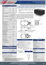
PC61 Single Pole Double Throw Interrupted Uninterrupted Thermal Current Rating (^th) Intermittent Current Rating: Rated Fault Current Breaking Capacity ('cn) 5ms Time Constant: Rated Fault Current Breaking Capacity (^cn) Resistive Load: Maximum Recommended Contact Voltages (Ue): Typical Voltage Drop per pole Mechanical M.T.B.F Coil Voltage Available (Us) (Rectifier board required for A. C.) Coil Power Dissipation: Highly Intermittent Rated Types Intermittently Rated types Prolonged Rated Types Continuously Rated Types Maximum Pull-In Voltage (Coil at 20" C) Guideline: Highly Intermittent Rated types ^ ~n0/ M Intermittently Rated types ~n0/ M Continuously Rated Types ~~0/ 11 Drop-Out Voltage Range 10 - 25% Us Typical Pull-In Time 15ms Typical Drop-Out Time (N/O Contacts to Open): (Subject to resistance value) Typical Contact Bounce Period Operating Ambient Temperature Guideline Contactor Weight: Auxiliary Details Auxiliary Thermal Current Rating Auxiliary Contact Switching Capabilities (Resistive Load): The PC61 is a miniature series single pole double throw contactor designed for printed circuit board mounting. Devised for both interrupted and uninterrupted loads, the PC61 is suitable for switching Resistive, Capacitive and Inductive loads. Typical applications include Telecommunication, UPS and other power conversion systems. Interrupted current - opening and closing on load with frequent switching (results in increased contact Uninterrupted current - no or infrequent load switching requirements (maintains a lower contact resistance). The PC61 features single pole double breaking main contacts with silver alloy tips, which are weld resistant, hard wearing and have excellent conductivity. The PC61 can be secured to the printed circuit board by means of an M4 bolt. Note: The PC range now incorporates the mounting board option, previously assigned to the MB range (existing MB part numbers remain valid). RED POSITIVE LABEL HERE WHEN MAGNETIC BLOWOUTS FITTED SQUARE COIL PINS NORMALLY CLOSED FIXED CONTACT OPTIONAL AUXILIARY FITTED HERE ENCLOSED CONTACT HOUSING " AUXILIARY CONTACT PINS NORMALLY OPEN FIXED CONTACT Current (Amperes) Uninterrupted Current Advised Connection Sizes for Maximum Continuous Current Circuit Board Tracks ^Rated suitable for Application^ |_ Note: Where applicable values shown are at 20°C * Please check our web site for product UL status § Normally Open contacts only - Normally Closed contacts are not designed to make and break current Performance data provided should be used as a guide only. Some de-rating or variation from figures may be necessary according to application. Thermal current ratings stated are dependant upon the size of conductor being used For further technical advice email: [email protected] Albright reserve the right to change data without prior notice Connection Diagram AUXILIARY CONTACT Magnetic Blowouts - High Powered7 X Magnetic Latching1" (Not fail safe) o M Closed Contact Housing* o EE Type (Steel Shroud) X AC Rectifier Board (Fitted) X Manual Override Operation X Key: Optional o Standard • Not Available X T Connections become polarity sensitive * Enclosed top cover standard when blowouts not fitted § Not Suitable with Mounting Base Albright International Ltd, Evingar Trading Estate, Ardglen Road, Whitchurch, Hampshire, RG28 7BB, UK E-mail: [email protected] [email protected] Web Site: www.albrightinternational.com PC61 Copyright ©2013 Albright International LTD
Open the catalog to page 1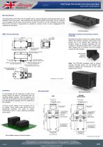
PC61 Single Pole Double Throw Normally Open Mounting Boards All configurations of the PC61 can be supplied with an optional separate mounting base which can be soldered to the circuit board. After soldering and washing the printed circuit board, the PC contactor can be plugged into the base and secured by means of an M4 nut on the underside of the board. Removal for servicing or replacement is possible by removal of the nut and unplugging the PC contactor from the base. RED POSITIVE LABEL HERE WHEN MAGNETIC BLOWOUTS FITTED COIL PINS- NORMALLY CLOSED FIXED CONTACT OPTIONAL AUXILIARY FITTED HERE...
Open the catalog to page 2All ALBRIGHT INTERNATIONAL catalogs and technical brochures
 About Albright
2 Pages
 SU190
SU1901 Page
 DC92 Monoblock, 2 x SW80
1 Page
 DC88P-100
1 Page
 SW61
SW611 Page
 Stud range
7 Pages
 SW80
SW801 Page


Archived catalogs


- Isolator switch
- Power contactor
- DC contactor
- Electromagnetic contactor
- AC contactor
- DC disconnector
- Motor contactor
- High-voltage contactor
- 1 NO contactor
- Reversing contactor
- Contactor for telecom applications
- Normally closed contactor
- Single-pole contactor
- Electromechanical contactor
- NO/NC contactor
- 2-pole contactor
- Capacitor switching contactor
- Power distribution contactor
- Contactor for the automotive industry