- Catalogs
- Aida S.r.l.
- dsf-c1-n1-n2-specs
dsf-c1-n1-n2-specs
1 /6Pages

dsf-c1-n1-n2-specs
1 /6Pages
Catalog excerpts

DSF-C1 series DSF-N1 series DSF-N2 series
Open the catalog to page 1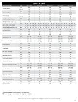
DSF-C1 MODELS Press Technical Data Tonnage Capacity Rated Tonnage Point Working Energy Slide Stroke Length (maximum) SPM @ Full Stroke Length (no load) Stroke Length, Fully Adjustable * (See AIDA for further examples) SPM @ Stroke Length Above (no load) Slide Adjustment Bolster Thickness Throat Depth Main Motor (SERVO) Power Supply Capacity Required Air Pressure Foundation Bolt Position (LR x FB) Inside Frame Dimension Floor to Top of Bolster (without mounts) Overall Dimension (LR x FB) Approx. Overall Height (without mounts) * Dimensions shown in inches rounded to the nearest tenth. ** Dimensions...
Open the catalog to page 2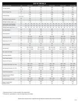
DSF-N1 MODELS Press Technical Data Tonnage Capacity Rated Tonnage Point Working Energy Slide Stroke Length (maximum) SPM @ Full Stroke Length (no load) Stroke Length, Fully Adjustable * (See AIDA for further examples) SPM @ Stroke Length Above (no load) Slide Adjustment Bolster Thickness Side Opening ** Main Motor (SERVO) Power Supply Capacity Required Air Pressure Foundation Bolt Position (LR x FB) Inside Frame Dimension Press Foot to Top of Bolster (without mounts) Overall Dimension (LR x FB) Approx. Overall Height (without mounts) * Dimensions shown in inches rounded to the nearest tenth....
Open the catalog to page 3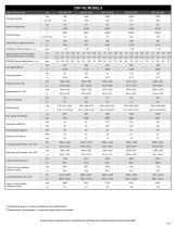
DSF-N2 MODELS Press Technical Data Tonnage Capacity Rated Tonnage Point Working Energy Slide Stroke Length (maximum) SPM @ Full Stroke Length (no load) Stroke Length, Fully Adjustable * (See AIDA for further examples) SPM @ Stroke Length Above (no load) Slide Adjustment Bolster Thickness Side Opening ** Main Motor (SERVO) Power Supply Capacity Required Air Pressure Foundation Bolt Position (LR x FB) Inside Frame Dimension Press Foot Top of Bolster (without mounts) Overall Dimension (LR x FB) Approx. Overall Height (without mounts) * Dimensions shown in inches rounded to the nearest tenth. **...
Open the catalog to page 4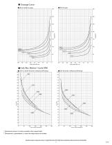
Tonnage Curve DSF-C1 & DSF-N1 series Position above BDC(mm) DSF-N2 series (At Maximum SPM Setting) 100 150 200 Stroke Length Setting(mm) 150 200 Stroke Length Setting(mm) * Dimensions shown in inches rounded to the nearest tenth. ** Dimensions in parentheses ( ) show the height above the bolster. Specifications subject to change without notice | © Copyright AIDA-America 2018. All Rights Reserved | Reproduction without permission from AIDA prohibited. 5
Open the catalog to page 5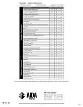
Standard / Optional Equipment ◎ Standard Equipment Equipment Details Hydraulic Overload Protector (HOLP) HOLP Lower Pressure Setting Device Electronic Crank Angle Indicator Die Height Indicator (Units: 0.01 mm) Motorized Slide Adjustment Preset Stop Point Selectors Forced Recirculation Lubrication System Control Panel Standard Equipment Main Operation Panel T-Stand, 2-Hand Operation Type, w/ Manual Step Feed Control Servo Driver MPSVC PLC (Programmable Logic Controller) HMI (Human-Machine Interface) Timing Switch: 4 Spare Cams Production Counters: Three-6-Digit Resettable Type Maintenance Counter:...
Open the catalog to page 6All Aida S.r.l. catalogs and technical brochures
 NC Specs
2 Pages
 DSF-C1-A
1 Page
 CHI
CHI2 Pages
 AIDA - Blanking line
9 Pages
 Total transfer knowledge
3 Pages
 Transfer press
2 Pages

Archived catalogs
 Servo Mechanical Presses
1 Page
 Slide Suspension Designs
4 Pages
 Press Balancing Systems
3 Pages
 Transfer Technology Systems
4 Pages
 Slide guide systems
4 Pages
 Reverse tonnage
8 Pages
 NC2 Gap Frame Presses
4 Pages
 NC1 Gap Frame Presses
6 Pages
 AIDA Srl COMPANY PROFILE
8 Pages
 AIDA PRODUCT BROCHURE
6 Pages


- Aida industrial press
- Industrial robot
- Aida hydraulic press
- Aida forming press
- Articulated robot
- 6-axis robot
- Automatic press
- Handling robot
- Vertical press
- Electric press
- Pneumatic press
- High-speed robot
- Cutting press
- Aida stamping press
- PLC-controlled press
- Aida frame press
- Aida mechanical press
- Bending press
- Compression press
- Press for the automotive industry