- Catalogs
- Agilent Technologies - Life Sciences and Chemical
- M9393A PXIe Performance Vector Signal Analyzer
M9393A PXIe Performance Vector Signal Analyzer
1 /31Pages

M9393A PXIe Performance Vector Signal Analyzer
1 /31Pages
Catalog excerpts

Performance Vector Signal Analyzer •••• •••• Datasheet Agilent Modular Products
Open the catalog to page 1
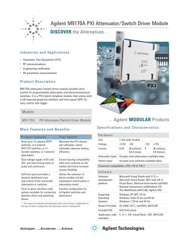
Applic ations • Aerospace and defense manufacturing and depot test • Wireless device design validation and manufacturing Whether your system supports a leading-edge design or a legacy platform, change is certain. Modular solutions are highly adaptable, and Agilent is taking flexibility farther with the M9393A PXIe performance vector signal analyzer. The M9393A is the realization of our microwave measurement expertise in modular form. It integrates core signal-analysis capabilities with hardware speed and accuracy, enabling you to tailor your solution to fit specific needs – today and tomorrow....
Open the catalog to page 2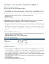
TECHNICA L S P EC IFIC A T IO N S A N D C H A R A C T E R I S T I C S De f i n i ti o n s f o r sp e ci fi cat i o ns Temperatures referred to in this document are defined as follows: • Full temperature range = Individual module temperature of 15 to 75 °C, as reported by the module, and environment temperature of 0 to 55 °C. • Controlled temperature range = Individual module temperature of 36 to 50 °C, as reported by the module, and environment temperature of 20 to 30 °C. Specifications describe the warranted performance of calibrated instruments. Data represented in this document are specifications...
Open the catalog to page 3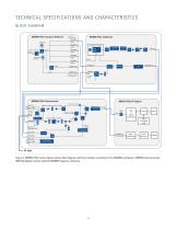
TECHNICA L S P EC IFIC A T IO N S A N D C H A R A C T E R I S T I C S B L OCK D I A G R A M M9300A PXIe Frequency Reference 100 MHz PLL Signal Processing ASIC Filter Bank Filter Bank Signal Conditioning Clock Generator Reserved for future functionality Figure 2. M9393A PXIe vector signal analyzer block diagram with four modules consisting of the M9308A synthesizer, M9365A downconverter, M9214A digitizer and the optional M9300A frequency reference.
Open the catalog to page 4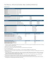
TECHNICA L S P EC IFIC A T IO N S A N D C H A R A C T E R I S T I C S F R E Q U E NCY Frequency range and resolution Option F08 Tuning resolution Analysis bandwidth 1 Maximum bandwidth Harmonic mixing mode Frequency switching speed 5, 6 List mode switching speed 7 Baseband frequency offset change Standard, nominal Arbitrary frequency change within: Standard, nominal Non-list mode switching speed 8 Baseband frequency offset change Arbitrary frequency change 1. Instantaneous bandwidth (1 dB bandwidth) available around a center frequency over which the input signal can be digitized for further analysis...
Open the catalog to page 5
TECH NICA L S P EC IFIC A T IO N S A N D C H A R A C T E R I S T I C S F R E Q U E N CY (C O N T’D ) Resolution bandwidth (RBW) Minimum RBW Maximum RBW (ENBW) Video bandwidth (VBW) Range 1 Hz to maximum RBW and wide open to 50 MHz VBW is implemented by averaging to achieve a similar variance reduction effect for the same VBW value. Frequency span Range 10. IF Dither ON only available with 89600 VSA software, option SSA.
Open the catalog to page 6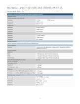
TECHNICA L S P EC IFIC A T IO N S A N D C H A R A C T E R I S T I C S F R E Q U E NCY (C O N T’D ) Frequency reference (M9300A PXIe frequency reference module) Reference outputs 100 MHz Out (Out 1 through Out 5) Amplitude Frequency accuracy Same as accuracy of internal time base or external reference input Internal timebase Accuracy ± [(time since last adjustment x aging rate) ± temperature effects ± calibration accuracy] Frequency stability Aging rate Daily < ±0.5 ppb/day, after 72 hours of warm-up < ±0.1 ppm/year, after 72 hours of warm-up < ±0.6 ppm/10yrs, after 72 hours of warm-up Achievable...
Open the catalog to page 7
TECHNICA L S P EC IFIC A T IO N S A N D C H A R A C T E R I S T I C S AMP L I T U D E Input level Max safe average total power Max RF input (specified performance) Expected input level setting Electronic attenuator Frequency range Attenuation range Step size Absolute amplitude accuracy 11 Frequency 12 Pre-amp bypass 15 Specification 11. Measured using a well matched input signal (8490D-020) attenuator. Module temperature within ± 3 °C of field alignment. 12. Frequency is exclusive on the start frequency and inclusive on the stop frequency. 13. Expected input level set to 6 dBm below 3.6 GHz....
Open the catalog to page 8
TECHNICA L S P EC IFIC A T IO N S A N D C H A R A C T E R I S T I C S AMP L I T U D E ( C O N T’D ) Amplitude repeatability and linearity Pre-amp OFF, typical Repeatability Linearity Power range Across any 20 MHz Across any 20 MHz 40 MHz in 40 MHz path in 160 MHz path IF phase linearity, typical 18, 19 Across any 20 MHz Across any 20 MHz 40 MHz in 40 MHz path in 160 MHz path IF bandwidth filter switching uncertainty 20 Specification Expected input level switching uncertainty 21 Pre-amp OFF 22 ≤ –5 dBm 16. Input level dBm, LO nulling run at ~1 GHz, 150 ms allowed for amplitude settling, measurement...
Open the catalog to page 9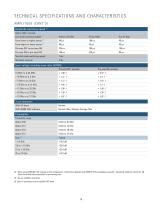
TECHNICA L S P EC IFIC A T IO N S A N D C H A R A C T E R I S T I C S AMP L I T U D E ( C O N T’D ) Amplitude switching speed 24 Option UNZ, nominal List mode switching speed From higher to lower power 25 Non-list mode switching speed Standard, nominal From lower to higher power Input voltage standing wave ratio (VSWR) Pre-amp OFF, nominal Trace detectors With IVI driver Normal, Max, Sample, Average, Min Preamplifier Frequency range Option F08 24. When using M9018A PXIe chassis (2-link configuration: 1x8 [factory default]) and M9037A PXIe embedded controller. Amplitude settled to within 0.1 dB....
Open the catalog to page 10
TECHNICA L S P EC IFIC A T IO N S A N D C H A R A C T E R I S T I C S DY NA M I C R A N G E SP EC IFIC ATIO N S Displayed average noise level (DANL) 27 Specification Gain compression (0.1 dB two-tone), nominal 28 Frequency 27. Expected input level = -60 dBm, Mixer level offset = 0 dBm, Noise Correction ON uses 100 averages, Conversion = auto, PeakToAverage = 0 dB. 28. Large signals can cause the analyzer to incorrectly measure on-screen signals because of two-tone gain compression. This specification tells how large an8interfering signal must be in order to cause a 0.1 dB change in a low power...
Open the catalog to page 11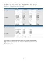
TECHNICA L S P EC IFIC A T IO N S A N D C H A R A C T E R I S T I C S DY NA M I C R A N G E SP EC IFIC ATIO N S (CONT’D) Third order intermodulation distortion (TOI) Frequency Pre-amp OFF Second harmonic distortion (SHI) Frequency Pre-amp OFF 29. Tone separation = 100 kHz, Expected input level = 3 dBm, Mixer offset level = 0 dB, PeakToAverage = 6 dB, Conversion type Auto 30. Tone separation = 100 kHz, Expected input level = –22 dBm, Mixer offset level = 0 dB, PeakToAverage = 6 dB, Conversion type Auto 31. Expected input level = 0 dBm 32. Expected input level = -30 dBm
Open the catalog to page 12All Agilent Technologies - Life Sciences and Chemical catalogs and technical brochures
 Agilent 280 Series AA Systems
12 Pages
 Inorganic Standards
40 Pages
 InfinityLab LC Supplies
148 Pages
 General Chromatography
164 Pages
 Sample Preparation (2018/2019)
144 Pages
 MS500
MS50012 Pages
 FLAME ATOMIC ABSORPTION SPECTROSCOPY
104 Pages
 Agilent training
27 Pages
 AGILENT VACUUM PRODUCTS CATALOG
536 Pages
 Vacuum Measurement Catalog
44 Pages
 AGILENT ION Pumps
53 Pages
 AGILENT DIFFUSION PUMPS
35 Pages
 AGILENT Rotary Vane Pumps
29 Pages
 Agilent InfinityLab LC Series
16 Pages
 3100 fractionator
8 Pages
 4200 MP-AES
12 Pages
 Agilent GPC/SEC Solutions
12 Pages
 Agilent?s biomass solutions
12 Pages
 X-ray Crystallography
12 Pages
 Agilent ProPulse NMR System
5 Pages
 An autosampler like no other
4 Pages
 Agilent U1450A/U1460A
19 Pages
 Agilent B1507A
22 Pages
 Agilent M9703A
16 Pages
 W1905 Radar Model Library
16 Pages
 M8048A ISI Channels
7 Pages
 Agilent J-BERT M8020A
27 Pages
 Agilent N8900 Series
10 Pages
 I/O Hardware
16 Pages
 Advanced Design System
16 Pages
 RF & Microwave Attenuators
4 Pages
 E4980AL Precision LCR Meter
8 Pages
 FieldFox Handheld Analyzers
8 Pages
 AFM/SPM Accessories
20 Pages
 VEE 9.32
24 Pages
 89600 VSA Software
9 Pages
 Command Expert
2 Pages
 E5061B Network Analyzer
8 Pages
 E5071C ENA Network Analyzers
18 Pages
 N9038A MXE EMI Receiver
2 Pages
 N9322C Basic Spectrum Analyzer
10 Pages
 Digital Multimeters
25 Pages
 M9361A PXI Downconverter
2 Pages
 Power Meters and Power Sensors
34 Pages
 E7515A UXM Wireless Test Set
2 Pages
 Agilent Power Products
31 Pages
 E5063A Network Analyzer
8 Pages
 Leak Detection Catalog
41 Pages
 Agilent 7820A GC brochure
8 Pages
 Agilent GC-MSD and QTOF
96 Pages
 Agilent GC-MSD 5977
39 Pages
 Agilent Intro BERLIN
24 Pages


Archived catalogs
 1290 Infinity Quaternary LC
24 Pages
 1260 Infinity Bio-inert
26 Pages
 Diffusion Pumps Catalog
37 Pages


- Pressure transmitter
- Analog pressure transmitter
- Agilent spectrometer
- Gas detector
- Membrane pressure transmitter
- Automatic tester
- Automatic test kit
- Sensitive element pressure transmitter
- Agilent spectrophotometer
- Agilent laboratory spectrometer
- Agilent chromatograph
- Agilent laboratory chromatograph
- Visible spectrophotometer
- Rugged tester
- Agilent mass spectrometer
- Compact spectrometer
- Real-time detector
- Benchtop spectrophotometer
- Process spectrometer
- Benchtop spectrometer