

Agilent B1507A

Agilent B1507A
The Agilent B1507A Power Device Capacitance Analyzer is designed for evaluating power device capacitance parameters such as Ciss, Coss, Crss, and Rg under various operating voltages, particularly for high-frequency devices made from materials like SiC and GaN.
- Measures input, output, and reverse transfer capacitances at high bias voltages.
- Supports independent terminal capacitance measurements and handles normally-on devices like SiC JFET or GaN FET.
- Measures internal gate resistance (Rg) and automates switching between leakage tests and capacitance measurements.
- Operates with voltage bias up to +/-3 kV.
- Capacitance measurement max bias: Gate ±100 V, Collector/Drain ±3000 V.
- Frequency range: 1 kHz to 1 MHz; Capacitance range: 100 fF to 1μF.
- Collector/Drain channel max output: Voltage ±3000 V, Current DC ±8 mA.
- Gate channel max output: Voltage ±100 V, Current DC ±100 mA.
- Accuracy specified under controlled conditions: Temperature 23 °C ± 5 °C, Humidity 20% to 70%.
- Self-calibration required after a 40-minute warm-up; Calibration period: 1 year.
- Temperature: +5°C to +40°C; Humidity: 20% to 70%, no condensation.
- Includes capacitance characteristics like Ciss, Coss, Crss, Cgs, Cgd, Cds, and static characteristics like gate leakage current and breakdown voltage.
Graphs show measurement accuracy for various capacitance parameters across different frequencies, highlighting error margins of 3%, 5%, 10%, and 20% under specified conditions.
The B1507A is a comprehensive tool for power device development, offering detailed capacitance characterization and aiding in the selection of optimal power devices for electronic circuit design.
Voltage compliance settings for current source mode are outlined, specifying power compliance levels based on voltage compliance (Vc) and output current (Io).
The High Voltage Source Measure Unit (HVSMU) has a voltage range of -3000 to 3000 V and a current range of -8 to 8 mA, with compliance limits to prevent device damage.
Details on pulse width and period settings for MPSMU and HVSMU, emphasizing that pulse peak and base values must have the same polarity when the pulse voltage exceeds 1500 volts.
The Multi-Frequency Capacitance Measurement Unit (MFCMU) covers a frequency range of 1 kHz to 5 MHz with specific accuracy and output signal levels.
The B1507A software suite supports power device characterization with features for I/V characteristics measurement, device power loss calculation, and capacitance measurement.
Detailed accuracy specifications for impedance, capacitance, and conductance measurements under specific conditions.
Details on terminal configurations and indicators for various measurement modes, along with software interfaces and operating software features.
Data display options include X-Y graph plotting, list display, and data variable display, with capabilities for overlay graph comparison and user-defined parameter display.
Sampling interval range for measurements varies from 100 μs to 65.535 s with different resolutions, specifying hold time and initial wait time, measurement time resolution, and other characteristics.
Various measurement control options such as single, repeat, append, and stop, along with SMU setting capabilities including limited auto-ranging and compliance functions.
Operating altitude from 0 m to 2,000 m, with storage up to 4,600 m. Power requirements include an AC voltage range of 90 V to 264 V and a line frequency of 47 Hz to 63 Hz.
Compliance with EMC and safety standards such as IEC 61326-1, IEC61010-1, and certifications including CE, cCSAus, C-Tick, and KC.
Dimensions and weight for the B1507A mainframe, selector, and test fixture are provided.
Includes measurement cables, system cables, a keyboard, mouse, stylus pen, power cables, and a manual & software CD-ROM.
Details on model numbers, options, documentation, calibration, and drive options, along with contact information for Agilent offices worldwide.
Agilent's three-year warranty, assurance plans, and ISO 9001:2008 certification, along with links to related products and services.
Catalog excerpts
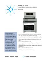
Power Device Capacitance Analyzer Data Sheet Automatically evaluate all power device capacitance parameters (including Ciss, Coss, Crss, and Rg) under a wide range of operating voltages to improve power device and power electronics circuit design performance • Measure transistor input, output and reverse transfer capacitances (Ciss, Coss, Crss, Cies, Coes, Cres) at high bias voltages • Measure independent terminal capacitances (Cgs, Cgd, Cds, Cge, Cgc, Cce) • Measure capacitances for normally-on devices such as SiC JFET or GaN FET • Measure internal gate resistance (Rg) • Measure capacitance continuously as the gate voltage varies from negative to positive • Easy to switch back and forth between leakage tests and capacitance measurements • Wide operation voltage bias up to +/-3 kV • Easy to use and fully automated measurement
Open the catalog to page 1
With the increasing use of power devices fabricated from emerging new materials such as SiC and GaN, switching power supplies are operating at increasingly higher frequencies. This makes accurate device capacitance characterization more important than ever before. The B1507A Power Device Capacitance Analyzer meets this need, providing a complete solution for the evaluation of power device capacitance (such as input, output, and reverse transfer capacitances). The B1507A can help power device development engineers maximize product value and performance by revealing detailed device characteristics....
Open the catalog to page 2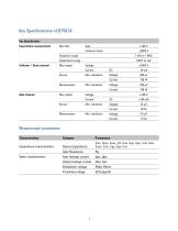
Key Specifications of B1507A Key Specification Max bias Capacitance measurement Frequency range Capacitance range Collector / Drain channel Gate channel Measurement parameters Characteristics Capacitance characteristics Device Capacitance Ciss, Coss, Coss_eff, Crss, Cgs, Cgd, Cds, Cies, Coes, Cres, Cge, Cgc, Cce, Gate Resistance Gate leakage current Igss, Iges Output leakage current Idss, Ices Breakdown voltage BVds, BVces Threshold voltage Static characteristics
Open the catalog to page 3
Capacitance measurement specifications B1507A capacitance measurement is achieved using the combination of an MFCMU module in the B1507A mainframe and the built-in device capacitance selector in the B1507A test fixture. 100 kO at SMU bias output resistance Voltage drop compensation function is available. Bypass capacitance in the capacitance selector Capacitance Withstand voltage Drain to Source Terminal 1 uF ±3000V Gate to Source Terminal 1 uF ±100V Measurement accuracy for 2-terminal device (Supplemental characteristics) Accuracy of this supplemental characteristics is defined at the output...
Open the catalog to page 4
Measurement accuracy for 3-terminal device (Supplemental characteristics) Accuracy of the following supplemental characteristics is defined at the output terminals inside the test fixture. Condition AC level: 30 mV rms, Dx < = 0.1 (Dx: Measurement value of D) Cgs measurement accuracy 3-terminal Cgs:Cds:Cgd= 1:1:1 1.E-06 1.E-07 Cgs measurement accuracy 3-terminal Cgs:Cds:Cgd= 1:0.1:0.01 1.E-06 1.E-07
Open the catalog to page 5
Cds measurement accuracy 3-terminal Cgs:Cds:Cgd = 1:1:1 1.E-06 1.E-07 Cds measurement accuracy 3-terminal Cgs:Cds:Cgd = 1:0.1:0.01 1.E-06 1.E-07
Open the catalog to page 6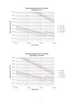
Cgd measurement accuracy 3-terminal Cgs:Cds:Cgd = 1:1:1 1.E-06 1.E-07 Cgd measurement accuracy 3-terminal Cgs:Cds:Cgd = 1:0.1:0.01 1.E-06 1.E-07
Open the catalog to page 7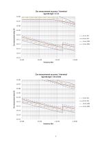
Ciss measurement accuracy 3-terminal Cgs:Cds:Cgd = 1:1:1 1.E-06 1.E-07 Ciss measuremet value (F) Ciss measurement accuracy 3-terminal Cgs:Cds:Cgd = 1:0.1:0.01 1.E-06 1.E-07 Ciss measuremet value (F)
Open the catalog to page 8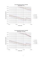
Coss measurement accuracy 3-terminal Cgs:Cds:Cgd = 1:1:1 1.E-06 1.E-07 Coss measuremet value (F) Coss measurement accuracy 3-terminal Cgs:Cds:Cgd = 1:0.1:0.01 1.E-06 1.E-07 Coss measuremet value (F)
Open the catalog to page 9
Output terminals for 3-terminal device Parameter Name Definition of 3-terminal device capacitances Symbol Description Cgs Capacitace between Base/Gate terminal and Emitter/Source terminal Cds Capacitace between Collector/Drain terminal and Emitter/Source terminal Cgd Capacitace between Base/Gate terminal and Collector/Drain terminal Crss Capacitace between Base/Gate terminal and Collector/Drain terminal Ciss Capacitace between Base/Gate terminal and Emitter/Source terminal and capacitance between Base/Gate terminal and Collector/Drain terminal Coss Capacitace between Collector/Drain terminal...
Open the catalog to page 10
Current/Voltage measurement specifications Current/Voltage measurement is achieved using the MPSMU module connected to Gate/Base terminal. The HVSMU module is connected to Drain/Collector terminal. The GNDU is connected to Source/Emitter terminal. MPSMU Gate Output Specifications Voltage range, resolution, and accuracy (high resolution ADC) Voltage Force Measure Force accuracy 1 range resolution resolution ±(% + mV) Maximum current 1. ± (% of reading value + offset value in mV) 2. 100 mA (Vo ≤ 20 V), 50 mA (20 V < Vo ≤ 40 V), 20 mA (40 V < Vo ≤ 100 V), Vo is the output voltage in Volts. Current...
Open the catalog to page 11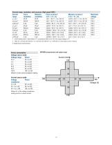
Current range, resolution, and accuracy (high speed ADC) Current Force Measure Force accuracy 1 range resolution resolution ±(% + A + A) ±1 nA 3 ±10 nA 3 ±100 nA 3 ±1 µA 3 ±10 µA ±100 µA ±1 mA ±10 mA ±100 mA 1. ±(%of reading value + xed offset in A + proportional offset in A), Vo is the output voltage in V.) 2. 100 V (Io ≤ 20 mA), 40 V (20 mA < Io ≤ 50 mA), 20 V (50 mA < Io ≤ 100 mA), Io is the output current in Amps. 3. Supplemental characteristics Power consumption Voltage source mode: Voltage range Power MPSMU measurement and output range 0.5 V 20 x Ic (W) 2V 20 x Ic (W) 5V 20 x Ic (W) 20...
Open the catalog to page 12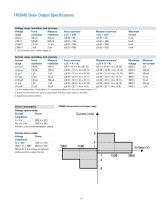
HVSMU Drain Output Specifications Voltage range, resolution, and accuracy Voltage Force Measure range resolution resolution Maximum current Maximum voltage 1. ±(% of reading value + offset voltage V) Current range, resolution, and accuracy Current Force Measure range resolution resolution ±10 nA 3 ±100 nA 3 ±1 µA 3 ±10 µA ±100 µA ±1 mA ±10 mA 1. ±(%of reading value + xed offset in A + proportional offset in A), Vo is the output voltage in V.) 2. Output current needs to be set at a value greater than the current shown in the table. 3. Supplemental characteristics Power consumption Voltage source...
Open the catalog to page 13All Agilent Technologies - Life Sciences and Chemical catalogs and technical brochures
 Agilent 280 Series AA Systems
12 Pages
 Inorganic Standards
40 Pages
 InfinityLab LC Supplies
148 Pages
 General Chromatography
164 Pages
 Sample Preparation (2018/2019)
144 Pages
 MS500
MS50012 Pages
 FLAME ATOMIC ABSORPTION SPECTROSCOPY
104 Pages
 Agilent training
27 Pages
 AGILENT VACUUM PRODUCTS CATALOG
536 Pages
 Vacuum Measurement Catalog
44 Pages
 AGILENT ION Pumps
53 Pages
 AGILENT DIFFUSION PUMPS
35 Pages
 AGILENT Rotary Vane Pumps
29 Pages
 Agilent InfinityLab LC Series
16 Pages
 3100 fractionator
8 Pages
 4200 MP-AES
12 Pages
 Agilent GPC/SEC Solutions
12 Pages
 Agilent?s biomass solutions
12 Pages
 X-ray Crystallography
12 Pages
 Agilent ProPulse NMR System
5 Pages
 An autosampler like no other
4 Pages
 Agilent U1450A/U1460A
19 Pages
 Agilent M9703A
16 Pages
 W1905 Radar Model Library
16 Pages
 M8048A ISI Channels
7 Pages
 Agilent J-BERT M8020A
27 Pages
 Agilent N8900 Series
10 Pages
 I/O Hardware
16 Pages
 Advanced Design System
16 Pages
 RF & Microwave Attenuators
4 Pages
 E4980AL Precision LCR Meter
8 Pages
 FieldFox Handheld Analyzers
8 Pages
 AFM/SPM Accessories
20 Pages
 VEE 9.32
24 Pages
 89600 VSA Software
9 Pages
 Command Expert
2 Pages
 E5061B Network Analyzer
8 Pages
 E5071C ENA Network Analyzers
18 Pages
 N9038A MXE EMI Receiver
2 Pages
 N9322C Basic Spectrum Analyzer
10 Pages
 Digital Multimeters
25 Pages
 M9361A PXI Downconverter
2 Pages
 Power Meters and Power Sensors
34 Pages
 E7515A UXM Wireless Test Set
2 Pages
 Agilent Power Products
31 Pages
 E5063A Network Analyzer
8 Pages
 Leak Detection Catalog
41 Pages
 Agilent 7820A GC brochure
8 Pages
 Agilent GC-MSD and QTOF
96 Pages
 Agilent GC-MSD 5977
39 Pages
 Agilent Intro BERLIN
24 Pages









Archived catalogs
 1290 Infinity Quaternary LC
24 Pages
 1260 Infinity Bio-inert
26 Pages
 Diffusion Pumps Catalog
37 Pages


- Pressure transmitter
- Analog pressure transmitter
- Agilent spectrometer
- Gas detector
- Membrane pressure transmitter
- Automatic tester
- Automatic test kit
- Sensitive element pressure transmitter
- Agilent spectrophotometer
- Agilent chromatograph
- Agilent laboratory spectrometer
- Agilent laboratory chromatograph
- Visible spectrophotometer
- Agilent mass spectrometer
- Rugged tester
- Compact spectrometer
- Benchtop spectrophotometer
- Benchtop spectrometer
- Industrial workstation
- Real-time detector