Catalog excerpts

Modular feeding technology 2016
Open the catalog to page 1
Highest quality feeding technology high grade, reliable, THE INTERNATIONAL CERTIFICATION NETWORK Afag GmbH Certified area Whole Company Feeding Technology for Industrial Automation Management System which fulfills the requirements of the following standard(s) /Roland Glausei THE INTERNATIONAL CERTIFICATION NETWORK Certified area Whole Company Components for assembly automation Feeding solutions Management System which fulfills the requirements of the following standard(s)
Open the catalog to page 2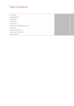
Table of contents Linear feeder Bowl feeder drives Feeding bowls Refilling units Control devices Afag-Chrome-Line feeding components Flex feeding Diagnostics and training Project-specific components Keyword directory
Open the catalog to page 4
4 Feeding technology 2016 afag.com
Open the catalog to page 5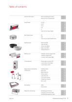
Linear feeder Micro-spreading technique Reactive force compensation Technical description Sub-structure linear feeder Sub-structure bowl feeder drives Refillable vibratoy hopper NVB Conveyor belt hopper NBB Refilling units Feeding bowls Bowl feeder drives Base plate Level control device Collecting container Bowl cover Feeding station Buffer control Flex Feeding Control device SIGA Afag-Chrome-Line feeding components Phase angle controller IRG Control device Smart Box Control devices
Open the catalog to page 6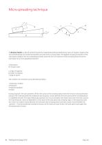
Micro-spreading technique A vibratory feeder is a device transforming electro-magnetically produced vibrations by means of magnet, magnet armature and leaf springs into mechanical vibrations and uses them to convey loads. The targeted conveying movement of the work piece is based on the micro-spreading principle, where the form of movement of the conveying device forces the work piece into a micro spreading movement. A Work piece B Conveyor track α Angle of trajectory β Angle of inclination γ Angle of ascent The conditions of movement can be described as follows: 1 Stationary condition 2...
Open the catalog to page 7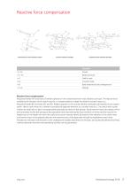
Reactive force compensation Conventional 2-mass vibration system Counter vibration principle Coupled counter-vibration principle Reactive forces Useful mass Counter mass Base attached to the underground Reactive force compensation Afag bowl feeder WV and linear LF feeders operate on the conventional twin-mass vibration principle. The reactive force created by the vibration of the useful mass (m1) is compensated by a larger foundation (counter) mass (m2). Afag bowl feeder BF and linear HLF and KLF feeders operate on the counter vibration principle with reactive force compensation. Here a...
Open the catalog to page 8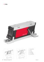
Track Cover Side plate Trim weight Linear feeder
Open the catalog to page 9
Linear feeder Linear feeder HLF-M Linear feeder HLF-P Sub-structure linear feeder
Open the catalog to page 10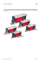
Linear feeder The Afag hybrid Magnet or piezo
Open the catalog to page 11
HLF - the new Afag generation of linear feeders stands for Hybrid Linear Feeder. Depending on application, the drive technology best suited for the project-specific requirements can be selected for this new type of linear feeder. The drive systems available include the familiar actuation based on an oscillating magnet (HLF-M) and a new patented piezoelectric drive (HLF-P). The mechanical interfaces are identical irrespective of the drive system. This allows the drive system to be changed easily. The advantages of the piezo driven linear feeder are particularly evident when feeding extremely...
Open the catalog to page 12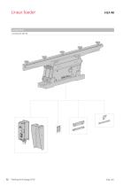
Linear feeder Compendium Accessories HLF-M
Open the catalog to page 13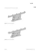
For fastening the rail to the HLF two variants are possible: Variant 1 Construction with side plate O Variant 2 Construction with side plate S
Open the catalog to page 14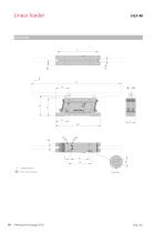
Linear feeder = Track center of gravity
Open the catalog to page 15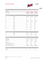
Technical data Dimensions Units Centre of gravity of rail Technical data Useful mass Weight device Protection class Reactive force compensation Vibrator frequency (electric) in Hz Note: Refer to p. 98 for appropriate control devices. Track not included in scope of supply Feeding technolog
Open the catalog to page 16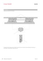
Linear feeder Compendium Mechanical connection of HLF feeders To realize tracks with a large maximum length, the useful and counter masses can be mechanically connected up to 4 HLF feeders and operated by a single control unit.
Open the catalog to page 17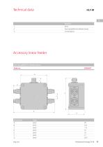
Technical data Four way splitter for vibration drives Control device Accessory linear feeder Four way splitter for vibration drives Order no.
Open the catalog to page 18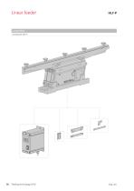
Linear feeder Compendium Accessories HLF-P
Open the catalog to page 19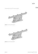
For fastening the rail to the HLF two variants are possible: Variant 1 Construction with side plate O Variant 2 Construction with side plate S
Open the catalog to page 20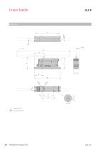
Linear feeder = Track center of gravity
Open the catalog to page 21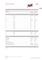
Technical data Dimensions Units Centre of gravity of rail Technical data Useful mass Weight device Protection class Reactive force compensation Vibrator frequency (electric) in Hz Note: Refer to p. 22 for appropriate control devices. Track not included in scope of supply
Open the catalog to page 22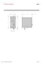
Control devices
Open the catalog to page 23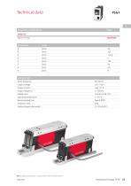
Technical data Piezoelectic control device Technical data Mains frequency Output voltage Output current Output frequency Enable input Operating temperature Recommended fuse Protection class External target value preset Note on selecting control device: Control unit PSG1 only for use with the HLF-P.
Open the catalog to page 24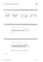
Accessory Linear feeders Alternative assembly variants for accessory
Open the catalog to page 25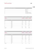
Technical data Alternative assembly variants for accessory Notation 5 Trim weight useful mass 6 Trim weight counterweight Dimensions Units Dimensions Units
Open the catalog to page 26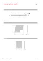
Accessory linear feeders Trim weight - Useful mass Trim weight - Counterweight Leaf spring
Open the catalog to page 27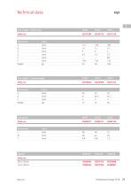
Technical data Trim weight - Useful mass Dimensions Units Trim weight - Counterweight Dimensions Units
Open the catalog to page 28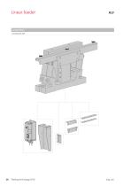
Linear feeder
Open the catalog to page 29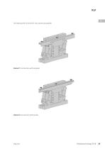
For fastening the rail to the KLF two variants are possible: Variant 1 Construction with side plate Variant 2 Construction with bracket
Open the catalog to page 30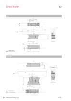
= Track center of gravity = Track center of gravity
Open the catalog to page 31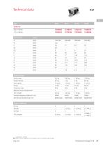
Technical data Dimensions Units Technical data Useful mass Weight device Protection class Reactive force compensation Trim weight Vibrator frequency (electric) in Hz Trim weights Note: Refer to p. 98 for appropriate control devices. Track not included in scope of supply.
Open the catalog to page 32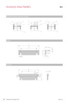
Accessory linear feeders Alternative assembly variants for accessory Side plate
Open the catalog to page 33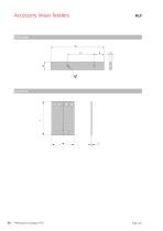
Accessory linear feeders Trim weight Leaf spring
Open the catalog to page 35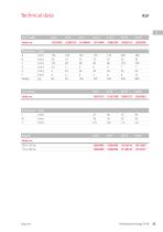
Technical data Leaf spring Dimensions Units
Open the catalog to page 36All Afag catalogs and technical brochures
-
Handling systems
8 Pages
-
Afag Product Overview
8 Pages
-
POSITIONING UNITS
17 Pages
-
Compact slides CS CS 6 - CS 25
21 Pages
-
cleanroom feeding systems
2 Pages
-
New Products
49 Pages


