- Catalogs
- Aeronaut Automation Pty Ltd
- Elektron Carbon Gantry Machine
Elektron Carbon Gantry Machine
1 /12Pages

Elektron Carbon Gantry Machine
1 /12Pages
Catalog excerpts

Tn.EMrLh.nu.n.E. Sa.iL TntrcLu.cHtm This is a basic outline of the way membrane sails are manufactured for people who are interested in getting into membrane sail production. Aeronaut supplies many mechanical and software parts of this system. For reasons of commercial confidentiality we cannot talk about customer's manufacturing processes in detail. However this overview covers almost all aspects of the process of membrane sail production so you can evaluate the commercial aspects of the process. The term "String Sails" is commonly used to describe membrane sails, the plotter is commonly referred to as a 'Stringer" and the process of laying the fibres is commonly called "Stringing". Apart from North's sails machines and sails made on a handful one-off in-house machines, almost all the other membrane or string sails around have been made on an Aeronaut machine, The process falls into the following sections. To begin with you need a CAD file containing the load paths or fibre paths of the design. This file may come complete from a sail design program, or may be produced with CAD software. Another program is used before manufacturing to produce the panels for stringing with loops developed between each path to connect them up into one or more composite In the manufacturing area, sections of Mylar film are laid on a table or floor, and taped together to form a flat panel somewhat larger than the outline of the finished panel. Yarns or fibres loaded up onto the "stringing head" which is fitted to the plotter. The plotter then traverses back and forwards over the film, laying the yarn following the paths in the CAD file. One or other glue processes is used to stick The base panel has to be large enough to accommodate the loops formed in the yarns where the yarn head does a 180° turn and heads back across the panel. The yarns are hardly ever supported on the yarn head since this would add unnecessary weight to the moving head, and would mean the yarn bobbins were small and needed frequent reloading. In practice, almost all yarn bobbins are supported some distance away from the yarn head, and the yarns are pulled off the end of the bobbin. When all the fibres are all laid, another layer of film is laid on top of the fibres, and laminated to produce a membrane. This is then trimmed to size and any finishing work done on the panel. Laminating can take many forms. In most cases the top layer of film is laid onto the base and fibre layer and air removed by preliminary vacuum bagging. This is followed by a roller applying heat and The laminated matrix is then trimmed to size, broad-seam added and the areas joined to form a sail. Software. Bear in mind that the membrane sail process has been around for 15 years or thereabouts and almost all the traditional sail design software other than SailPack cannot develop complete thread- line paths. So there are a lot of people designing sails who have no way of working in 3D in their familiar sail design program. Therefore there are three main approaches for developing the thread-line TJcLfcrrLCÍii-t Ttu.ttrmu.ti.trn. ~ 4-6 TEPKO ROAD TERREY HILLS NSW 2084 AUSTRALIA
Open the catalog to page 1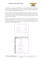
One approach is to use existing sail design software and develop 2D flat panels. These 2D panels are imported into sail specific program, lined up and the load or thread-line paths developed in this software. Since the 2D panels have shaped edges or broad-seam, it is not possible to completely overlap panels, and any thread-line paths must break across the 2D panel edges. SailPack is capable of importing 2D panels and developing thread-lines just as easily as it develops paths on its own 3D moulds. Another specialised program used for this is the Carlson Fibrepath software. This software is used...
Open the catalog to page 2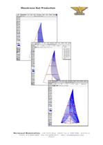
TÈe.rcrn.cLu.t Ttu.-ttrmujti.trn. ~ 4-6 TEPKO ROAD TERREY HILLS NSW 2084
Open the catalog to page 3
Tn.EMrLh.nu.n.E. Sa.iL TntrcLu.cHtm The resulting paths are exported to another program for developing loops etc. In the past, loop generation has actually been done by hand, especially in Asian plants where labour is cheap, and boredom free. A second approach to the developing thread-lines is to do all the design in a CAD program. This is possible, but great care has to be taken to make sure that the paths are suitable for looping. Often, the sort order of the paths can get confused in CAD software and make looping difficult or impossible. We've lately done quite a lot of work on routines to...
Open the catalog to page 4
Tn.EMrLh.nu.n.E. Sa.iL TntrcLu.cHtm 1. The original MEK based Sobstad Genesis process. This is the first process, developed by Sobstads about 15 years ago. The Mylar film is coated with glue, often by hand using a paint roller. The fibres are wetted with MEK solvent in the stringing head on the plotter. As the solvent wet yarns are laid on the film, they cut into the glue coating and stick. This process is probably the nastiest process around in terms of the chemicals. The machines are very simple and relatively low cost. Almost all of them are narrow (< 2000 mm wide). This means that the widest...
Open the catalog to page 5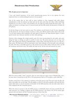
Membrane Sail Production Why the glue process is important. I have only limited experience of the actual manufacturing process, but in my opinion the most important factor in commercialising the process is lay-up speed. One of the reasons that we have sold so many machines to Asia compared with other plotter manufacturers is that our plotters are faster and can lay more yarns than the others. older technology machines lay 3-4 yarns at a time. I do not believe you can make any money laying this many yarns... not unless your plotter is moving at least 3-4 metres/second, and that falls outside the...
Open the catalog to page 6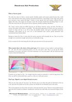
Wide or Narrow panels The other key choice is wide or narrow panels. Initially, people used narrow panels because they could more easily laminate them using existing conventional laminators, and perhaps at that stage many panels were necessary to get a good sail shape. I think it is now agreed, that with modern, relatively flat sail shapes, that only a few seams are necessary to give the necessary broad-seam and flying shape in a sail. (This does mean that the 3DL process with its expensive moulds is perhaps redundant.) The "Asian" narrow panel wet MEK processes are all labour intensive, messy...
Open the catalog to page 7All Aeronaut Automation Pty Ltd catalogs and technical brochures
 Elektron Laser Z Neo
2 Pages
 Elektron Laser ZP
2 Pages
 Tangent brochure
2 Pages
 Digital Pressure Gauge
1 Page
 Mikron Cutter
2 Pages
 Aeronaut Ink Jet Marking
1 Page
 Aeronaut Cam-Lock Tools
2 Pages


- Challenge Power Transmission cutting machine
- Challenge Power Transmission CNC cutting machine
- Challenge Power Transmission laser cutting machine
- Challenge Power Transmission automatic cutting machine
- Challenge Power Transmission cutting machine for industrial applications
- Challenge Power Transmission knife cutting machine
- Challenge Power Transmission high-precision cutting machine
- Challenge Power Transmission high-speed cutting machine
- Fabric cutting machine
- Challenge Power Transmission high-performance cutting machine
- Challenge Power Transmission compact cutting machine
- Rotary blade cutting system
- Challenge Power Transmission bridge cutting machine
- Challenge Power Transmission high-power cutting machine
- Challenge Power Transmission marking cutting machine
- Challenge Power Transmission cutting machine with water cooling
- Gantry type cutting machine
- Textile cutting machine
- Cutting tool
- Cutting head