- Catalogs
- ADZ NAGANO GmbH
- EI-000029-B
EI-000029-B
1 /3Pages

EI-000029-B
1 /3Pages
Catalog excerpts

EI-000029-B Customer information Pressure switch with integrated galvanic isolation Electronic switch with “unpowered closed” feature The pressure switch consists of two switch channels. Each channel is equipped with two parallel paths 1. an electronic FET-switch (main path) 2. a relay with dry contacts (path for unpowered situation) When unpowered, the relay (2) is closed, the FET-switch is bypassed. A current flows through the pressure switch device (PIN C/F and E/D). In the unpowered state, the switch is in NC-status. On power-up, the signal conditioner section takes control over both switching paths. The electronic switch becomes “CLOSE” – afterwards the Relay becomes “OPEN”. From now no longer the current flows through the relay but through the FET-switch. The signal conditioner section now controls the FET-switch based on the applied pressure. On power-down, the relay contacts become “CLOSE” and the unpowered FET-switch is bypassed again.
Open the catalog to page 1
EI-000029-B Feature sheet Each of the two integrated switching channels features four switching modes (see below): - Normally1 Open, - Normally1 Closed, - Window Mode – Normally1 Open, - Window Mode – Normally1 Closed. 1: Normally means: surrounding pressure applied. Each channel transits its switching state according to the measured pressure. Optionally, switching delay times can be applied. They are based on milliseconds and can be set for each channel separately. The current “drawn” by the application circuitry is permanently monitored. In case, the current exceeds the overcurrent limit (typically...
Open the catalog to page 2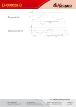
Overcurrent limit Tolerance current limit ADZ NAGANO GmbH, confidential
Open the catalog to page 3All ADZ NAGANO GmbH catalogs and technical brochures


- Pressure transmitter
- Analog pressure transmitter
- Level probe
- Liquid level sensor
- Waterproof pressure transmitter
- Membrane pressure transmitter
- Stainless steel pressure transmitter
- Relative pressure transmitter
- Analog level sensor
- Digital pressure transmitter
- Waterproof pressure switch
- Gas pressure transmitter
- Process pressure transmitter
- IP65 pressure transmitter
- Temperature transmitter
- Differential pressure transmitter
- Stainless steel level sensor
- Explosion-proof pressure transmitter
- IP68 level sensor