
Catalog excerpts
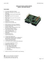
July 25, 2005 ZDR150EE Series DIGIFLEX® DIGITAL SERVO DRIVES MODEL: ZDR150EE12A8LDC FEATURES: • • • • • • • • • • • • • • • • • • • Fully digital, state-of-the-art design Space Vector Modulation and vector control technology 20kHz Digital current loop with programmable gain settings PIDF velocity loop with 100 microsecond update rate PID + FF position loop with 100 microsecond update rate Hall sensor + encoder or encoder-only based commutation Surface-mount technology Small size, low cost, ease of use RS232 interface for setup and configuration Windows© based setup software with built-in 8-channel digital scope Operates in torque, velocity or position mode with programmable gain settings Programmable profiling in all modes Fully configurable current, voltage, velocity and position limits. Step & direction mode for stepper replacement Encoder following with programmable gear ratio 3 programmable digital inputs 2 programmable differential inputs, configurable as step & direction, master encoder, or secondary encoder for dual loop operation 3 programmable digital outputs 12-bit reference input or programmable analog input • • • Four quadrant regenerative operation Separate logic supply input Extensive built-in protection against: • over-voltage (programmable) • under-voltage (programmable) • short-circuit: phase-phase, phase-ground • over-current • over-temperature • Optional mounting card MC1XZDR for easy interfacing ADVANCED MOTION CONTROLS 3805 Calle Tecate, Camarillo, CA 93012 Tel: (805) 389-1935, Fax: (805) 389-1165 Page 1 of 12
Open the catalog to page 1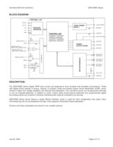
ADVANCED MOTION CONTROLS ZDR150EE Series BLOCK DIAGRAM: ZDR150EE...LDC RX/+RX TX/+TX RS232/485 INTERFACE -RX -TX LOGIC POWER LOGIC POWER SUPPLY GROUND GND GROUND CONTROLLER CURRENT CONTROL TORQUE CONTROL VELOCITY CONTROL POSITION CONTROL +5V 5K PROGR. INPUT 1..3 GND HIGH VOLTAGE MOTOR A POWER OUTPUT STAGE +PROGR. INPUT 4,5 STEP+, DIR+, AUX ENC A+/B+ MOTOR B MOTOR C 5K PROGR. OUTPUT 1...3 SGND 1K 6.67K +REF -REF + 6.67K 1K Refr. MOT ENC A+ MOT ENC A- MOTOR FEEDBACK +5V I/O INTERFACE -PROGR. INPUT 4,5 STEP-, DIR-, AUX ENC A-/B- MOT ENC B+ MOT ENC BMOT ENC I+ MOT ENC I+5V 5K HALL A,B,C GROUND...
Open the catalog to page 2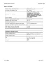
ADVANCED MOTION CONTROLS ZDR150EE Series SPECIFICATIONS: POWER STAGE SPECIFICATIONS ZDR150EE12A8LDC DC SUPPLY VOLTAGE (HV IN) 20…60 VDC 5 VDC (+/- 5%) @ 0.4A + current consumption of feedback and I/O. CAUTION: make sure the +5V IN is applied, prior to applying the HV IN. Applying HV IN before the +5V IN may cause damage to the drive. LOGIC SUPPLY VOLTAGE PEAK CURRENT 12A (8.6Arms) MAXIMUM CONTINUOUS CURRENT 6A (4.3Arms) MINIMUM LOAD INDUCTANCE 250 µH SWITCHING FREQUENCY 20 kHz HEATSINK (BASEPLATE) TEMPERATURE RANGE 0 to 65 ºC, disables at 65 ºC POWER DISSIPATION AT CONTINUOUS CURRENT See...
Open the catalog to page 3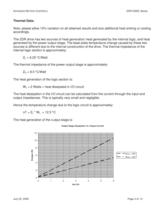
ADVANCED MOTION CONTROLS ZDR150EE Series Thermal Data: Note: please allow 10% variation on all obtained results and size additional heat sinking or cooling accordingly. The ZDR drive has two sources of heat generation: heat generated by the internal logic, and heat generated by the power output stage. The base plate temperature change caused by these two sources is different due to the internal construction of the drive. The thermal impedance of the internal logic section is approximately: ZL = 6.25 °C/Watt The thermal impedance of the power output stage is approximately: ZO = 8.5 °C/Watt...
Open the catalog to page 4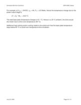
ADVANCED MOTION CONTROLS ZDR150EE Series For example, at V bus = 24VDC, Iout = 4A, P O = 3.6 Watts. Hence the temperature change due to the power output stage is: ∆T = ZO * WO = 30.6 °C The total base plate temperature change is 43.1 °C. Hence in a 25 °C ambient, the drive would shut down due to drive over temperature (65 °C). Additional heat sinking and/or cooling needs to be sized such that the base plate temperature stays below 65 °C to avoid over-temperature drive shutdown. July 25, 2005 Page 5 of 12
Open the catalog to page 5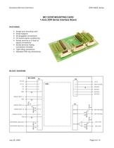
ADVANCED MOTION CONTROLS ZDR150EE Series MC1XZDR MOUNTING CARD 1-Axis ZDR Series Interface Board FEATURES: • • • • • Single axis mounting card Small footprint All pluggable connections On-board signal conditioning Screw terminal or D-Sub for signal connections • Screw terminal mating connectors included • Tight fitting connectors • Standard DIN tray dimensions BLOCK DIAGRAM: MC1XZDR P1 RX/+RX TX/+TX 13 -RX -TX P2 11 1 ZDR... +5V IN 4, 5 HIGH VOLTAGE 12 2, 3 GROUND 14 11, 12 MOTOR A 9, 10 MOTOR B 7, 8 MOTOR C 3, 4, 19 GND PROGR. INPUT 1..3 8, 9, 10 GND 3, 4, 19 +5V 10K 15, 17 +PROGR. INPUT...
Open the catalog to page 6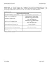
ADVANCED MOTION CONTROLS ZDR150EE Series DESCRIPTION: The MC1XZDR mounting card is designed to host a ZDR Series DigiFlex® servo drive. This mounting card offers convenient pluggable screw terminals and D-Sub connectors for easy interfacing. D-sub connectors are compatible with DR100EE series. A logic LED and power LED indicate supply status. SPECIFICATIONS: MECHANICAL SPECIFICATIONS MOTOR AND POWER CONNECTOR 5-position 5.08 mm spaced header* LOGIC SUPPLY CONNECTOR 3-position 5.08 mm spaced header* FEEDBACK CONNECTORS INPUT/OUTPUT CONNECTORS SERIAL INTERFACE CONNECTOR SIZE (without drive or...
Open the catalog to page 7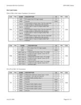
ADVANCED MOTION CONTROLS ZDR150EE Series PIN FUNCTIONS: P3A & P3B & CN3- Motor Feedback Connectors: CON. PIN NAME 1 +5V 5V output from 5V logic supply 2 GND 3 +Hall A 4 -Hall A 5 +Hall B 6 -Hall B 7 +Hall C 8 -Hall C Ground Commutation sensor input. Can be used with single ended or differential Hall sensors. Leave open in case of single ended Hall sensors. Commutation sensor input. Can be used with single ended or differential Hall sensors. Leave open in case of single ended Hall sensors. Commutation sensor input. Can be used with single ended or differential Hall sensors. Leave open in...
Open the catalog to page 8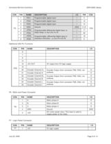
ADVANCED MOTION CONTROLS CON. PIN NAME 1 PDI1 2 ZDR150EE Series I/O PIN Programmable digital input I 11 PDI2 Programmable digital input I 12 3 PDI3 Programmable digital input I 13 4 GND Ground GND 2,16 5 +PDI4 17 -PDI4 Programmable differential digital input, or Step+/Step- or Aux Enc A+/A- I 6 I 26 7 +PDI5 18 -PDI5 Programmable, differential digital input or Direction+/Direction - or Aux Enc B+/B- I 8 P5 DESCRIPTION I CON. 9 CN2 Additional CN2 Pin Functions: CON. PIN NAME 6 - 14 - 15 +5V OUT 19 - 20 Encoder Channel A+ 21 Encoder Channel A- 22 Encoder Channel B+ 23 Encoder Channel B- 24...
Open the catalog to page 9All Advanced Motion Controls catalogs and technical brochures
-
dc201e60a40nac
12 Pages
-
dpcania-060a400
11 Pages
-
dpcantr-015b200
10 Pages
-
dprnlie-060a800
11 Pages
-
dr100ee15a40nac
7 Pages
-
dr101ee30a40ndc
7 Pages
-
dzxralte-040l080
8 Pages
-
mc1xdzc02-qd
9 Pages
-
ps50a
4 Pages
-
se10a40
8 Pages
-
srst400
4 Pages
-
sx30a8
8 Pages
-
zbdc6a6
5 Pages
-
zbh6a6
9 Pages
-
z6a6
5 Pages
-
z12a8
5 Pages
-
25a17
2 Pages
-
20a20
9 Pages
-
Mounting Card MC1XDZ01
13 Pages
-
INDUCTIVE FILTER CARDS
9 Pages
-
PS16 SERIES
5 Pages
-
PS2X3 and PS4X3 SERIES
5 Pages
-
PS300 SERIES
4 Pages
-
DPQNNIE-020B080
10 Pages
-
DPCANTE-020B080
10 Pages
-
Analog Servo Drive S16A8
8 Pages
-
Analog Servo Drive BE15A8-H
8 Pages
-
Analog Servo Drive 12A8
9 Pages
-
Analog Servo Drive AZ6A8
7 Pages
Archived catalogs
-
Capabilities Brochure
6 Pages


