
Catalog excerpts
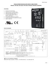
BROKEN LIME REPRESENTS LED GREEN - NORMAL OPERATION, LED RED- FAULT RECOMMENDED SETTING FOR CURRENT NODE - POT1 FULLY CON, POT3 FULLV CU AMPLIFIERS ARE SHIPPED IN CURRENT MODE IN A DISABLED STATE NITH THE OUTPUT S1J2-6 MUST BE ON FOR PROPER OPERATION ON HALL UELOCITY MODE FOR OTHER SNITCH FUNCTIONS SEE SWITCH DESCRIPTION t OPTIONAL USER INSTALLED THROUGH HOLE COMPONENTS NOTE: THE RESISTOR AND CAPACITOR UALUES FOR R363, R%3, R563 AND C365, C465, C565 RESPECTIUELV MUST IE IDENTICAL.
Open the catalog to page 1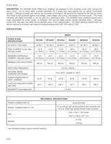
SE30A Series DESCRIPTION: The SE30A20 Series PWM servo amplifiers are designed to drive brushless motors with 3 phase sine wave current. An on board digital controller generates the 3 phase sine wave signals from an optical "incremental encoder". Although encoders are used for the sinusoidal commutation, Hall sensors are required for the start up routine. This model is fully protected against over-voltage, under-voltage, over-current, over-heating and short-circuits. This model interfaces with digital controllers or can be used as a stand-alone drive. The SE30A20 series amplifiers require...
Open the catalog to page 2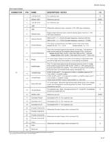
SE30A Series PIN FUNCTIONS: CONNECTOR PIN NAME DESCRIPTION / NOTES 1 +10V @ 3 mA For customer use O 2 SIGNAL GND Reference ground SGND 3 -10V @ 3 mA For customer use O 4 +REF 5 -REF Differential reference input, maximum ±15V, 20K input resistance I 6 Velocity Input Single ended reference input, external velocity signal, maximum ±15V, 10K input resistance I 7 Velocity Monitor SW2-3=OFF; 1 V = 25 kHz Encoder frequency, maximum 250 KHz I/O O SW2-3=ON; 1 V = 175 kHz Encoder frequency, maximum 1.75 MHz Current Monitor This signal is proportional to the RMS current in the motor leads. Models...
Open the catalog to page 3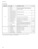
SE30A Series PIN FUNCTIONS: CONNECTOR PIN NAME 1 HALL 1 2 HALL 2 3 HALL 3 4 Encoder Channel A+ 5 Encoder Channel A- 6 Encoder Channel B+ 7 Encoder Channel B- 8 Encoder Channel I+ 9 Encoder Channel I- 10 DESCRIPTION / NOTES I/O Differential Encoder Input I Differential Encoder Input I Differential Encoder Input (Not Required) I Controller Line 1* Connected to P1-18. For customer use. O Controller Line 2* Connected to P1-19. For customer use. O 12 Signal GND Reference ground 13 +5V @ 250mA For customer use. Note: the total current on P1-15 and P2-13 combined should not exceed 250 mA. O 14...
Open the catalog to page 4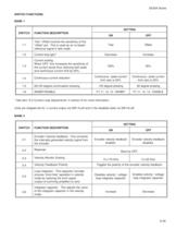
SE30A Series SWITCH FUNCTIONS: BANK 1 SETTING SWITCH FUNCTION DESCRIPTION 1-1 Test / Offset controls the sensitivity of the "offset" pot. This is used as an on-board reference signal in test mode. 1-2 Current loop gain* 1-3 Current scaling. When OFF, this increases the sensitivity of the current sense thus reducing both peak and continuous current limit by 50%. 1-4 Continuous current reduction 1-5 60/120 degree commutation phasing 1-6 INHIBIT/ENABLE ON OFF Test Offset Decrease Increase 100% 50% Continuous / peak current limit ratio is 50% Continuous / peak current limit ratio is 25% 120...
Open the catalog to page 5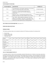
SE30A Series POTENTIOMETER FUNCTIONS: POTENTIOMETER DESCRIPTION TURNING CW Pot 1 This potentiometer is the loop gain adjustment in the velocity mode. Turn this pot fully CCW in current mode. Pot 2 Current limit. This potentiometer adjusts both the continuous and peak current limit while maintaining a selected ratio. Pot 3 Reference in gain. This potentiometer adjusts the ratio between input signal and output variables (current, velocity). Increases reference input gain Pot 4 Test / Offset. Used to adjust any imbalance in the input signal or in the amplifier. When SW1-1 (DIP switch) is ON,...
Open the catalog to page 6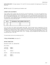
SE30A Series APPLICATION NOTE: For proper operation, P1-6, and P2-14 must be connected to the signal ground if they are not being used. SET-UP: See section "G" for engineering and installation notes. CURRENT LIMIT ADJUSTMENTS: These amplifiers feature separate peak and continuous current limit adjustments. The current limit adjustment Pot 2 adjusts both peak and continuous current limit at the same time. It has 12 active turns and one inactive turn at each end. This pot is approximately linear. Thus, to adjust the current limit turn the potentiometer counter-clockwise to zero, then turn...
Open the catalog to page 7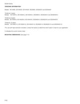
SE30A Series ORDERING INFORMATION: Models: SE10A8X, SE10A20X, SE10A40X, SE30A8X, SE30A20X and SE30A40X *Divide by 4 option Models: SE10A8X-4, SE10A20X-4, SE10A40X-4, SE30A8X-4, SE30A20X-4 and SE30A40X-4 *Divide by 8 option Models: SE10A8X-8, SE10A20X-8, SE10A40X-8, SE30A8X-8, SE30A20X-8 and SE30A40X-8 *Divide by 16 option Models: SE10A8X-16, SE10A20X-16, SE10A40X-16, SE30A8X-16, SE30A20X-16 and SE30A40X-16 *For use with high-resolution encoders, contact the factory to determine which option is best for your application X indicates the current revision letter. MOUNTING DIMENSIONS: See page...
Open the catalog to page 8All Advanced Motion Controls catalogs and technical brochures
-
dc201e60a40nac
12 Pages
-
dpcania-060a400
11 Pages
-
dpcantr-015b200
10 Pages
-
dprnlie-060a800
11 Pages
-
dr100ee15a40nac
7 Pages
-
dr101ee30a40ndc
7 Pages
-
dzxralte-040l080
8 Pages
-
mc1xdzc02-qd
9 Pages
-
ps50a
4 Pages
-
srst400
4 Pages
-
sx30a8
8 Pages
-
zbdc6a6
5 Pages
-
zbh6a6
9 Pages
-
z6a6
5 Pages
-
zdr150ee12a8ldc
12 Pages
-
z12a8
5 Pages
-
25a17
2 Pages
-
20a20
9 Pages
-
Mounting Card MC1XDZ01
13 Pages
-
INDUCTIVE FILTER CARDS
9 Pages
-
PS16 SERIES
5 Pages
-
PS2X3 and PS4X3 SERIES
5 Pages
-
PS300 SERIES
4 Pages
-
DPQNNIE-020B080
10 Pages
-
DPCANTE-020B080
10 Pages
-
Analog Servo Drive S16A8
8 Pages
-
Analog Servo Drive BE15A8-H
8 Pages
-
Analog Servo Drive 12A8
9 Pages
-
Analog Servo Drive AZ6A8
7 Pages
Archived catalogs
-
Capabilities Brochure
6 Pages


