
Catalog excerpts
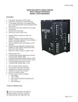
DC201E Series DIGIFLEX® DIGITAL SERVO DRIVES WITH CANopen INTERFACE MODEL: DC201E60A40NAC FEATURES: • • • • • • • • • • • • • • • • • • • • • • • Fully digital, state-of-the-art DSP design Brushed DC, brushless AC drive technology 10 kHz digital current loop, 5 kHz digital velocity loop, 5 kHz digital position loop with programmable gain settings Encoder and Hall sensor feedback for sinusoidal commutation Surface-mount technology Small size, low cost, ease of use Isolated CAN bus interface for setup and networking Supports CANopen communication protocol (DS301) and Device Profile for Drives and Motion Control commands (DSP-402) CAN bus address and bit rate selection via DIPswitches Windows© based DigiFlex® DriveWare setup software via CAN interface (operates with third party PC-to-CAN interface) Operates in torque, velocity or position mode Single encoder input 3 programmable isolated digital inputs (sinking), sourcing inputs optional (-SRC). 3 programmable isolated digital outputs (sinking) Dedicated isolated limit and home switch inputs 2 programmable analog inputs (14-bit) 1 programmable analog output (10-bit) Off-line 3-phase 240VAC operation Four quadrant regenerative operation Integrated shunt regulator and resistor Provision for external shunt resistor Bi-color LED status indicator Extensive built-in protection against: § over-voltage § under-voltage • short-circuit: phase-phase, phase-ground § over-current § over-temperature * Photo for reference only. ADVANCED MOTION CONTROLS 3805 Calle Tecate, Camarillo, CA 93012 Tel: (805) 389-1935, Fax: (805) 389-1165 Page 1 of 12
Open the catalog to page 1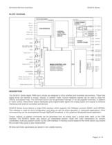
ADVANCED MOTION CONTROLS DC201E Series BLOCK DIAGRAM: DC201E60A40NAC ISOLATION ISOLATION LOGIC POWER SUPPLY CAN_V+ CAN_H SHUNT REG. CAN INTERFACE INT. RESIST. GNDCAN FUSE CAN_L EXT. RESIST. EXT. RESIST. CONTROL LOGIC AND PROTECTION CIRCUIT RTERM_CAN SHIELD_CAN FUSE AC1 FUSE AC2 FUSE AC3 MOTOR A DRIVE ENABLE 10K POWER OUTPUT STAGE GNDIO MOTOR B MOTOR C 10K I/O ISOLATION FAULT RESET, HOME, POS LIMIT, NEG LIMIT GNDIO PROGR. INPUT 1..3 10K GNDIO MOT ENC A+ MOT ENC AMOT ENC B+ MOT ENC BMOT ENC I+ MOT ENC I- GNDIO MAIN CONTROLLER PROGR. OUTPUT 1..3 CURRENT CONTROL TORQUE CONTROL VELOCITY CONTROL...
Open the catalog to page 2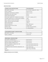
ADVANCED MOTION CONTROLS DC201E Series SPECIFICATIONS: POWER STAGE SPECIFICATIONS DC201E60A40NAC AC SUPPLY VOLTAGE 40 – 270 VAC, 3-phase, 50 – 60 Hz PEAK CURRENT 60A (42.4 Arms) MAXIMUM CONTINUOUS CURRENT 30A (21.2 Arms) MINIMUM LOAD INDUCTANCE 600 µH SWITCHING FREQUENCY 20 kHz HEATSINK (BASEPLATE) TEMPERATURE RANGE 0 to 65 ºC, disables at 65 ºC POWER DISSIPATION AT CONTINUOUS CURRENT 400W MIN. UNDER-VOLTAGE SHUTDOWN 55 VDC MAX. OVER-VOLTAGE SHUTDOWN 439 VDC BUS CAPACITANCE 1650 µF SHUNT RESISTOR 20Ω, 100W internal SHUNT SWITCH-ON VOLTAGE Programmable SHUNT FUSE 5A Motor Delay @ 250VAC AC...
Open the catalog to page 3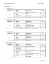
ADVANCED MOTION CONTROLS DC201E Series PIN FUNCTIONS: C1 – AC Supply Connector: CONNECTOR PIN 1 NAME DESCRIPTION AC1 I/O I AC supply input. 40 – 270 VAC, 3phase. 2 3 AC3 4 CASE GND Case ground 5 NC Not connected - NAME DESCRIPTION I/O 1 HV DC bus output O 2 PGND DC bus ground PGND 3 EXT. SHT External shunt resistor O 4 EXT SHT. External shunt resistor O 5 INT. SHT. Jumper Jumper for internal shunt resistor - NAME DESCRIPTION I/O 1 MA Motor phase A O 2 MB Motor phase B O 3 MC Motor phase C O 4 PGND DC bus ground PGND 5 C1 AC2 I HV DC bus output O NAME DESCRIPTION I/O I GND C2 – Shunt and DC...
Open the catalog to page 4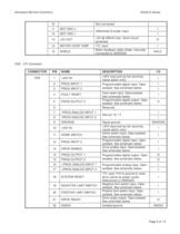
ADVANCED MOTION CONTROLS DC201E Series 10 - Not connected 11 MOT ENC I+ 12 MOT ENC I- 13 +5V OUT 14 MOTOR OVER TEMP 15 SHIELD Differential Encoder Input +5V @ 400mA max. Short-circuit protected. TTL input Motor feedback cable shield. Internally connected to GNDSGN I I O I SHLD CN2 – I/O Connector: CONNECTOR PIN NAME DESCRIPTION CN2 1 +24V IN +24V input pull-up (for sourcing inputs option only) 2 PROG INPUT 1 3 PROG INPUT 3 4 FAULT RESET 5 PROG OUTPUT 2 6 - 7 -PROG ANALOG INPUT 1 8 -PROG ANALOG INPUT 2 9 GNDSGN 10 +24V IN 11 HOME SWITCH 12 PROG INPUT 2 13 DRIVE ENABLE 14 PROG OUTPUT 1 15...
Open the catalog to page 5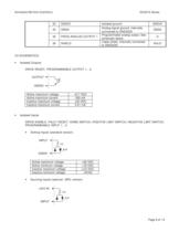
ADVANCED MOTION CONTROLS DC201E Series 23 GNDIO 24 GNDA 25 PROG ANALOG OUTPUT 1 26 SHIELD Isolated ground Analog signal ground. Internally connected to GNDSGN Programmable analog output. See schematic below. Cable shield. Internally connected to GNDSGN GNDIO GNDA O SHLD I/O SCHEMATICS: • Isolated Outputs DRIVE READY, PROGRAMMABLE OUTPUT 1…3 OUTPUT GNDIO Active maximum voltage Active maximum current Inactive maximum voltage Inactive maximum current • +0.7 VDC 200 mA +30 VDC 0.01 mA Isolated Inputs DRIVE ENABLE, FAULT RESET, HOME SWITCH, POSITIVE LIMIT SWITCH, NEGATIVE LIMIT SWITCH,...
Open the catalog to page 6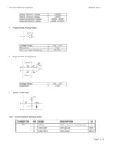
ADVANCED MOTION CONTROLS DC201E Series Active maximum voltage Active minimum voltage Inactive maximum voltage Inactive minimum voltage • Programmable Analog Output Voltage Range Resolution Minimum Load Resistance • +10VDC –5VDC +24VIN + 5VDC +24VIN –2.5VDC -10V…+10V 10-bit 2K Ohm Programmable Analog Inputs 0.01uF 10K 10K 10K + - 10K 10K 0.01uF Voltage Range Resolution • 10V…+10V 12-bit System Reset Input +5V 14K 1K 5.6VZ 0.1uF CN1 - Communications Interface (CAN): CONNECTOR PIN NAME DESCRIPTION I/O CN1 2 CAN_L CAN _L bus line (dominant low) 3 CAN_GND CAN ground GND 5 CAN_SHLD CAN shield...
Open the catalog to page 7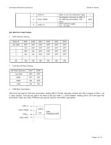
ADVANCED MOTION CONTROLS DC201E Series 7 CAN_H 8 CAN_TERM 9 CAN_H bus line (dominant high) Termination. Connect to CAN_H for CAN bus termination (120 Ohm) CAN external supply 7.5…13 VDC CAN_V+ I GND I DIP SWITCH FUNCTIONS: • CAN Address Setting Node-ID SW1 SW2 SW3 SW4 SW5 SW6 Via CAN OFF OFF OFF OFF OFF OFF 1 ON OFF OFF OFF OFF OFF 2 OFF ON OFF OFF OFF OFF 3 ON ON OFF OFF OFF OFF ON ON ON ON ON ON … 63 • CAN Bus Bit Rate Setting Bit Rate (bits/sec) SW8 Via CAN OFF OFF 500K OFF ON 250K ON OFF 125K • SW7 ON ON CAN Bus Termination SW10 can be used for CAN bus termination. Setting SW10 ON will...
Open the catalog to page 8All Advanced Motion Controls catalogs and technical brochures
-
dpcania-060a400
11 Pages
-
dpcantr-015b200
10 Pages
-
dprnlie-060a800
11 Pages
-
dr100ee15a40nac
7 Pages
-
dr101ee30a40ndc
7 Pages
-
dzxralte-040l080
8 Pages
-
mc1xdzc02-qd
9 Pages
-
ps50a
4 Pages
-
se10a40
8 Pages
-
srst400
4 Pages
-
sx30a8
8 Pages
-
zbdc6a6
5 Pages
-
zbh6a6
9 Pages
-
z6a6
5 Pages
-
zdr150ee12a8ldc
12 Pages
-
z12a8
5 Pages
-
25a17
2 Pages
-
20a20
9 Pages
-
Mounting Card MC1XDZ01
13 Pages
-
INDUCTIVE FILTER CARDS
9 Pages
-
PS16 SERIES
5 Pages
-
PS2X3 and PS4X3 SERIES
5 Pages
-
PS300 SERIES
4 Pages
-
DPQNNIE-020B080
10 Pages
-
DPCANTE-020B080
10 Pages
-
Analog Servo Drive S16A8
8 Pages
-
Analog Servo Drive BE15A8-H
8 Pages
-
Analog Servo Drive 12A8
9 Pages
-
Analog Servo Drive AZ6A8
7 Pages
Archived catalogs
-
Capabilities Brochure
6 Pages


