


TI-F50

TI-F50
Catalog excerpts
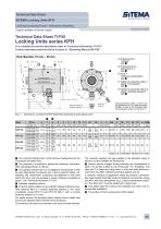
Technical Data Sheet TI-F50 Locking Units series KFH For a detailed functional description refer to“Technical Information TI-F10". Further important practical advice is given in “Operating Manual BA-F50". © Pressure port L “release” see 0 © Pressure port LL, alternative to L see @ © Ports T “pressure compensation” see 0 © Holder for proximity switch 1, signal “rod clamped” see 0 © Holder for proximity switch 2, signal “clamping released” see 0 Fig. 1: Dimensions Locking Unit KFH (CAD-files download at www.sitema.com) O The nominal holding force F is the minimum holding force for dry or hydraulic-oil wetted rods. 0 The pressure p is required to release the clamping. The admissible operating pressure is 160 bar. 0 As supplied, pressure port LL is plugged by a plug screw. It may be used alternatively to pressure port L and is useful for filling / airbleeding. We recommend connecting auto-bleeders to the ports which are not in use (not supplied in scope of delivery; available as option - see “Technical Information TI-Z10”). o Hydraulic operating volume 0 Proximity switch holders are provided for standard inductive proximity switches (M12 x 1 nominal switching distance 2 mm, flush mountable), except KFH 18 and KFH 25: M8 x 1 with a nominal switching distance of 1.5 mm. For easier service, the proximity switch holders have a depth stop and are pre-adjusted when delivered from the factory. The switches only need to be inserted to the stop and then clamped. The proximity switches are not supplied in the standard scope of delivery, but are available as accessories. o Internal volume changes during switching are compensated at ports T. An air filter is fitted to one of the ports T for “breathing”. The other port T is closed by a plug screw. In a dry and clean factory environment, this offers sufficient protection against dust etc. If, however, moisture or aggressive media are present, a pressureless hose instead of the filter must be installed to connect the Locking Unit KFH with clean atmosphere (e.g. a clean pressureless container). The other port T must be sealed with a plug screw. 7 Lock plates keep the Locking Unit released and need to be removed after installation. o The surface of the housing parts is ZnNi coated. Subject to modification without prior notice SITEMA GmbH & Co. KG . G.-Braun-StraUe 13 . D-76187 Karlsruhe . Phone: +49(0)721/98661-0 . Fax: -11 . www.site
Open the catalog to page 1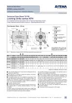
Technical Data Sheet TI-F50 Locking Units series KFH For a detailed functional description refer to“Technical Information TI-F10". Further important practical advice is given in “Operating Manual BA-F50". © Pressure port L “release” see © © Pressure port LL, alternative to L see @ © Ports T “pressure compensation” see 6 © Holder for proximity switch 1, signal “rod clamped” see 0 © Holder for proximity switch 2, signal “clamping released” see 0 Due to tolerances, ports 1, 2 and T can be displaced up to +/-5° relative to drawn position as well as the threaded holes G2 to pressure ports L/LL and...
Open the catalog to page 2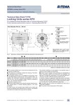
Technical Data Sheet TI-F50 Locking Units series KFH For a detailed functional description refer to“Technical Information TI-F10". Further important practical advice is given in “Operating Manual BA-F50". ©Pressure port L “release” see © © Pressure port LL alternative to L see @ © Ports T “pressure compensation” see 6 © Holder for proximity switch 1, signal “rod clamped” see 0 ©Holder for proximity switch 2, signal “clamping released” see 0 Fig. 3: Dimensions Locking Unit KFH (CAD-files download at www.sitema.com) o The nominal holding force F is the minimum holding force for dry or hydraulic-oil...
Open the catalog to page 3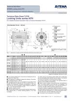
Subject to modification without prior notice O The nominal holding force F is the minimum holding force for dry or hydraulic-oil wetted rods. 0 The pressure p is required to release the clamping. The admissible operating pressure is 160 bar. 0 As supplied, pressure port LL is plugged by a plug screw. It may be used alternatively to pressure port L and is useful for filling / airbleeding. We recommend connecting auto-bleeders to the ports which are not in use (not supplied in scope of delivery; available as option - see “Technical Information TI-Z10”). o Hydraulic operating volume 0 Proximity...
Open the catalog to page 4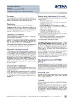
Purpose The Locking Unit KFH is used as an infinitely variable lock on piston rods for cylinders or other clamping rods. The Locking Unit KFH absorbs axial forces in both load directions. Axial play The load is held free from axial play in load direction 1. In standard designs, the load is also free from axial play in load direction 2 as long as the load does not exceed 80 % of the nominal holding force (F). In the case of exceeding, the axial play in load direction 2 is about 0.1 - 0.3 mm. Operating conditions The Locking Unit KFH is designed to operate in normal clean and dry workshop atmosphere. Operation...
Open the catalog to page 5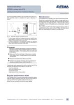
J WARNING! Risk due to slowed discharge of pressure medium! Slowed discharge of the pressure medium may cause a dangerous situation. The clamping then only locks with a time delay. K Make sure that the discharge of the pressure medium from pressure port L is not impaired by any additional components. K Route all connection lines without any kinks. K If there is any danger of kinking, take appropriate precautions (protective tube, thicker hose, etc.). If a particular quick response time of the Locking Unit KFH is required, the following preconditions must be met: • short line distances • fast...
Open the catalog to page 6All Advanced Machine & Engineering catalogs and technical brochures
 KTE40-1000
2 Pages
 P-SERIE
4 Pages
 F-SERIES
4 Pages
 B20 Dimensions Spring base
2 Pages
 F60 Dimensions, type KFHA
6 Pages
 Z10 Auto-Bleeder
3 Pages
 STB10 Rod Attachment STB
3 Pages
 M11 Dimensions MVA
1 Page
 KRM Safety Catcher
3 Pages
 Company Brochure
15 Pages
 F23 KFPD for torque
3 Pages
 Product Brochure
8 Pages
 TI-S11
1 Page
 TI-B11
1 Page
 TI-A12
1 Page
 TI-A11
2 Pages
 TI-A10
7 Pages
 OppSystem-Section
24 Pages
 Accessories-Section
8 Pages
 tripoxyMINERAL
32 Pages
 aptoCLAMP
22 Pages
 microCLAMP
40 Pages
 triCENTRO
34 Pages
 powerCLAMP & 5axes powerCLAMP
90 Pages
 OTT - Worm Gears
162 Pages
 Shaft-Measurement
4 Pages
 Air-To-Electronic_Columns
4 Pages
 SPIETH Catalog
100 Pages
 SPEEDCUT
4 Pages
 AMLOCK_RLN Pneumatic Rodlock
16 Pages
 AMSAW Rail Saw Brochure
2 Pages
 AMSAW S-Series
6 Pages
 Amsaw P-Series
4 Pages
 AME Company Overview
20 Pages
 AMROK Workholding Solutions
23 Pages
 AMROK Tombstones
16 Pages
 AMROCK Modular Workholding
80 Pages


