


TI-A11

TI-A11
- Load Capacity: The admissible force (M) exerted by the mass on the Safety Catcher is specified, with holding forces ranging from 2xM to 3.5xM.
- Pressure Requirements: A pressure of 40 bar is necessary to release the clamping, increasing to 60 bar if a spring base is installed. The maximum operating pressure is 250 bar.
- Proximity Switches: Holders are provided for standard inductive proximity switches, with specifications for mounting and depth adjustment.
- Surface Treatment: Housing parts are primed black with corrosion protection wax on the front sides.
- Installation: Pressure ports L and LL are used for release and air-bleeding, with recommendations for auto-bleeder installation.
- Maintenance: Internal volume changes are managed via port T, which is equipped with an air filter. In environments with moisture or aggressive media, a pressureless hose should be used.
- Ensure proper installation of proximity switches and pressure ports to maintain operational efficiency.
- Regularly check and maintain the air filter or pressureless hose to prevent contamination.
Catalog excerpts
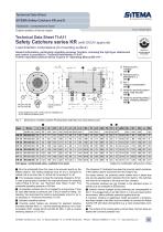
bold types = preferential sizes, available from stock Subject to modification without prior notice O M is the admissible force the mass to be secured exerts on the Safety Catcher. The holding (braking) force for dry or hydraulic-oil wetted rods is not less than 2 x M but will not exceed 3.5 x M. 0 The necessary pressure to keep the clamping released is 40 bar. In case a spring base is installed, the required pressure for releasing without lifting is 60 bar, see “Technical Data Sheet TI-A20”. The admissible operating pressure is 250 bar. 0 As supplied, pressure port LL is plugged by a plug screw. It may be used alternatively to pressure port L and is useful for filling / airbleeding. We recommend to install an auto-bleeder at port LL (or L) as described in “Technical Information TI-Z10”. O Hydraulic operating volume 0 Proximity switch holders are provided for standard inductive proximity switches (M12 x 1, nominal switching distance 2 mm, flush mountable, NOC; except KR 25 and KR 28: M8 x 1 with a nominal switching distance of 1.5 mm). The dimension T3 indicates how deep the proximity switch immerses in the Safety Catcher measured from the holder's top. For easier service, the proximity switch holders have a depth stop and are pre-adjusted when delivered from the factory. The switches only need to be inserted to the stop and then clamped. The proximity switches are not included in the standard scope of delivery but are available as accessories. o Internal volume changes during switching are compensated at port T. It is plugged with an air filter which, in a dry and clean factory environment, offers sufficient protection against dust etc. If, however, moisture or aggressive media are present, a pressureless hose instead of the filter must be installed to connect the Safety Catcher KR with clean atmosphere (e.g. a clean pressureless container). 7 The surface of the housing parts is primed black, the front sides are treated with corrosion protection wax. SITEMA GmbH & Co. KG . G.-Braun-StraUe 13 . D-76187 Karlsruhe . Phone: +49(0)721/98661-0 . Fax: -11 .
Open the catalog to page 1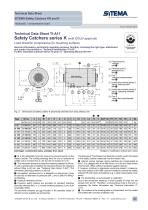
bold types = preferential sizes, available from stock Subject to modification without prior notice O M is the admissible force the mass to be secured exerts on the Safety Catcher. The holding (braking) force for dry or hydraulic-oil wetted rods is not less than 2 x M, but will not exceed 3.5 x M. 0 The necessary pressure to keep the clamping released is 40 bar. In case a spring base is installed, the required pressure for releasing without lifting is 60 bar, see “Technical Data Sheet TI-A20”. The admissible operating pressure is 250 bar. 0 As supplied, pressure port LL is plugged by a plug...
Open the catalog to page 2All Advanced Machine & Engineering catalogs and technical brochures
 KTE40-1000
2 Pages
 P-SERIE
4 Pages
 F-SERIES
4 Pages
 B20 Dimensions Spring base
2 Pages
 F60 Dimensions, type KFHA
6 Pages
 Z10 Auto-Bleeder
3 Pages
 STB10 Rod Attachment STB
3 Pages
 M11 Dimensions MVA
1 Page
 KRM Safety Catcher
3 Pages
 Company Brochure
15 Pages
 F23 KFPD for torque
3 Pages
 Product Brochure
8 Pages
 TI-F50
6 Pages
 TI-S11
1 Page
 TI-B11
1 Page
 TI-A12
1 Page
 TI-A10
7 Pages
 OppSystem-Section
24 Pages
 Accessories-Section
8 Pages
 tripoxyMINERAL
32 Pages
 aptoCLAMP
22 Pages
 microCLAMP
40 Pages
 triCENTRO
34 Pages
 powerCLAMP & 5axes powerCLAMP
90 Pages
 OTT - Worm Gears
162 Pages
 Shaft-Measurement
4 Pages
 Air-To-Electronic_Columns
4 Pages
 SPIETH Catalog
100 Pages
 SPEEDCUT
4 Pages
 AMLOCK_RLN Pneumatic Rodlock
16 Pages
 AMSAW Rail Saw Brochure
2 Pages
 AMSAW S-Series
6 Pages
 Amsaw P-Series
4 Pages
 AME Company Overview
20 Pages
 AMROK Workholding Solutions
23 Pages
 AMROK Tombstones
16 Pages
 AMROCK Modular Workholding
80 Pages


