- Company
- Products
- Catalogs
- News & Trends
- Exhibitions
TI-A10
1 /7Pages

TI-A10
1 /7Pages
Catalog excerpts
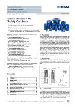
SiTEMA ■ Expertise in Safety Technical Information SITEMA Safety Catchers Hydraulic or pneumatic actuation English translation of German original Technical Information TI-A10 Safety Catchers 0 high holding force by self-reinforcing clamping 0 hydraulic or pneumatic actuation 0 officially certified by DGUV as restraint device for presses, injection moulding machines, rubber and plastics machines For further information on technical data and optional accessories, please see: • “Technical Data Sheet TI-A11” (hydraulic pressure versions: series KR, K) • “Technical Data Sheet TI-A12” (pneumatic pressure versions: series KRP) • “Technical Data Sheet TI-A13” (hydraulic tensile versions: series KR/T, K/TA) • “Technical Data Sheet TI-A14” ("pneumatic tensile versions: series KRP/T) • “Technical Data Sheet TI-A20” (spring bases for pressure versions) • “Technical Data Sheet TI-A21” (spring bases for tensile versions) • “Technical Data Sheet TI-A30” (flanges for Safety Catchers and spring bases) For information on the DGUV approval and EC type-examination certificate, please see: • “EC Type-examination Certificate TI-A40” A detailed description of control, mounting and performance test of the SITEMA Safety Catchers can be found in: • “Operating Manual BA-A11” (hydraulic versions) • “Operating Manual BA-A12” (pneumatic versions) 1 Purpose Safety Catchers are used where protection of personnel and accident prevention must be achieved in connection with raised loads or tools in case of failure of load-bearing machine parts. This may e.g. be a leakage or breakdown of a hydraulic or pneumatic pressure system. Safety Catchers catch falling masses infinitely variable at any position of the stroke, in a mechanically secure and absolutely reliable manner. The design principle of the self-reinforcing clamping ensures an extremely high safety level. Safety Catchers serve as mechanical restraint devices for static loads. For this static holding, the Safety Catcher is certified according to the testing principle GS-HSM-02 of the DGUV (testing and certification body of the statutory accident insurance and prevention institution in Germany). For further information see “EC type-examination certificate TI-A40”, internet download: www.sitema.com. 2 Function SITEMA Safety Catchers release by applying hydraulic or pneumatic pressure and clamp at pressure loss. The kinetic energy of the falling mass is then used to generate the holding force. The clamping rod (1) is surrounded by the housing (2) in which several wedged clamping jaws (3), each with one slide lining (4) and one brake lining (5), are assembled. When pressure (p) is applied to the plungers (8), the clamping jaws are held in a raised position so that the rod can move freely. The springs (6) are compressed in this position. SITEMA GmbH & Co. KG . G.-Braun-StraUe 13 . D-76187 Karlsruhe . Phone: +49(0)721/98661-0 . Fax: -11 .
Open the catalog to page 1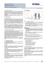
2.1 Secure the load The Safety Catcher secures the load as soon as pressure is released from the plungers (8), Fig. 1. Then the action of the springs (6), Fig. 1 causes the clamping jaws (3), Fig. 1 to clamp the rod (1), Fig. 1 firmly, whereby an initial friction contact between rod and clamping sleeve is achieved (contact condition). At this point, the Safety Catcher secures the load but has not yet taken the load. 2.2 Take the load The holding force, however, is not built up until the rod has been moved by the load. Due to the self-reinforcing static friction at the rod, the clamping systems...
Open the catalog to page 2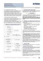
4.2 Actuation with a 3/2-way valve In most applications an actuation as suggested in Fig. 2 is used. During every operational cycle, the 3/2-way valve is actuated electrically and releases the Safety Catcher. In all other operational conditions, as well as in cases of power failure, pressure line breakage, emergency stop, etc. the Safety Catcher becomes effective, secures the rod and/or stops the load. If necessary the valve can also be switched by another safety signal, e.g. speeding, contouring error, etc. 4.3 Monitoring by proximity switches Proximity switch 1 “load secured” signals the secure...
Open the catalog to page 3
To ensure longer service life, the following operating modes should be avoided: • frequent dynamic braking • incorrect operation of the (press)cylinder with the clamp engaged • driving the rod against the load direction without applying pressure simultaneously Based on the results of fatigue tests, it can be assumed that under usual operating conditions (type of use 1 and occasionally type of use 2), the holding force will not drop below the nominal value after several years in use. Even after lots of clamping cycles, no relevant changes in the diameter or surface quality will be observed on...
Open the catalog to page 4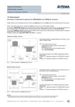
13 AttachmentOverview of attachment options for PRESSURE and TENSILE versions Safety Catchers can be integrated into the machine as stationary units or as mobile units moving with the load to be secured. When choosing the right series, consider the load that acts on the rod and the Safety Catcher. In the case of PRESSURE versions, the load presses the Safety Catcher onto the machine frame. The load is transferred via the mounting surface of the Safety Catcher into the machine frame. PRESSURE versions are: series KR, KRP, K. In the case of TENSILE versions the load pulls the Safety Catcher away...
Open the catalog to page 5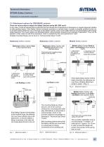
13.1Attachment options for PRESSURE versions There are various ways to attach the Safety Catchers series KR, KRP and K. In any case, it must be ensured that no side load can be induced due to tolerances in dimensions or angular alignment relative to other guiding means. If the Safety Catcher is directly mounted to a cylinder head, it usually is properly centered to the rod. In all other setups either the rod or the body of the Safety Catcher must not be rigidly fixed but mounted floating with enough radial clearance. Four basic options are illustrated below, using hydraulic presses as an example...
Open the catalog to page 6All Advanced Machine & Engineering catalogs and technical brochures
 KTE40-1000
2 Pages
 P-SERIE
4 Pages
 F-SERIES
4 Pages
 B20 Dimensions Spring base
2 Pages
 F60 Dimensions, type KFHA
6 Pages
 Z10 Auto-Bleeder
3 Pages
 STB10 Rod Attachment STB
3 Pages
 M11 Dimensions MVA
1 Page
 KRM Safety Catcher
3 Pages
 Company Brochure
15 Pages
 F23 KFPD for torque
3 Pages
 Product Brochure
8 Pages
 TI-F50
6 Pages
 TI-S11
1 Page
 TI-B11
1 Page
 TI-A12
1 Page
 TI-A11
2 Pages
 OppSystem-Section
24 Pages
 Accessories-Section
8 Pages
 tripoxyMINERAL
32 Pages
 aptoCLAMP
22 Pages
 microCLAMP
40 Pages
 triCENTRO
34 Pages
 powerCLAMP & 5axes powerCLAMP
90 Pages
 OTT - Worm Gears
162 Pages
 Shaft-Measurement
4 Pages
 Air-To-Electronic_Columns
4 Pages
 SPIETH Catalog
100 Pages
 SPEEDCUT
4 Pages
 AMLOCK_RLN Pneumatic Rodlock
16 Pages
 AMSAW Rail Saw Brochure
2 Pages
 AMSAW S-Series
6 Pages
 Amsaw P-Series
4 Pages
 AME Company Overview
20 Pages
 AMROK Workholding Solutions
23 Pages
 AMROK Tombstones
16 Pages
 AMROCK Modular Workholding
80 Pages


