- Catalogs
- Advanced Machine & Engineering
- B20 Dimensions Spring base
B20 Dimensions Spring base
1 /2Pages

B20 Dimensions Spring base
1 /2Pages
Catalog excerpts
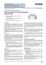
Spring bases for Safety series KSP 0 allow a release without lifting the load after minor lowering of the load 0 compensate for lateral misalignment between axis guide and clamping rod 0 also fit pneumatic Safety Locks series KRGP Purpose For reasons of safety, SITEMA Safety Brakes can usually only be released if their clamping system is not under load. For a detailed function description and an explanation of the different operating conditions, please refer to “Technical Infor-mationen TI-B10”. As long as the Safety Brake only secures the load and does not take the load, the clamping can be released by applying pressure at pressure port L “release”. Spring bases can compensate for a minor lowering of the load, making it possible to release the clamping without lifting the load. Use in practice If the vertical axis of a machine overshoots after reaching its top cut-off position or moves slightly downwards for any particular reason (e. g. due to leakage in the driving cylinders), the Safety Brake is subjected to a partial load. In practice this means that the axis must first be raised before a downward movement is possible. This effect can be avoided by not bolting the Safety Brake directly to the machine frame but rather on a spring-base. The advantages of the spring bases are: • The axis does not need to be lifted before a downward movement when minor lowering occurs during cyclic operation. • The spring base compensates for lateral misalignment between the axis guide and the clamping rod. Other compensating measures are not necessary in this case. Function The housing (1) Fig. 1 is securely fixed to the machine frame (4) Fig. 1 over the flange plate (5) Fig. 1. The bottom plate (2) Fig. 1 bears the Safety Brake and is securely fixed to it. When released (i. e. not under load) the Safety Brake and the bottom plate are pressed upward by the spring (3) Fig. 1 against the stop. The bottom plate is free to move vertically (stroke “h”) as well as horizontally (radial play “X”) against the machine frame (4) Fig. 1 . If the load should settle slightly (due to leakage, for example) while the Safety Brake is engaged, only the spring force of the SITEMA GmbH & Co. KG . G.-Braun-StraUe 13 . D-76187 Karlsruhe . spring base is exerted on the Safety Brake. In this case, the Safety Brake can be released without an upward movement. Only when the lowering movement exceeds the stroke length “h”, the full weight of the load will be taken by the Safety Brake. Now it is only possible to release the Safety Brake after a short upward movement. Note: The overall distance after which the load will be secured mechanically is increased by the distance h (for h see Table 1). This amount is to be taken into consideration when making safety analyses for engineering purposes. H The release pressure (using a spring base) for standard designs is 4.5 bar. Pressure must be supplied via a flexible line. The spring bases are fitted with an internal protection against torsion to prevent the pneumatic hoses from kinking or squeezing. Order and mounting If the spring base and the Safety Brake are ordered together, the spring base is factory-mounted under the Safety Brake, ready for use. All spring bases are also available separately. The spring bases are supplied fully assembled and just need to be attached on the attachment side of the Safety Brake. The control of the Safety Brake is not affected by the spring base, see “Technical Informationen TI-B10”. Attachment There are two alternatives for attaching the spring bases to the machine frame: • direct screw mounting using the threaded holes and drilling patterns arranged identically to the ones of the Safety Brake • with a mounting flange which engages with the externally attached shoulder All fixation elements that carry the load need to be dimensioned for 3.5 x admissible load (M). (Attachment screws are not included in the scope of delivery.) Bore holes with the correct dimensions (see Table 1) need to be provided in the machine frame.
Open the catalog to page 1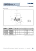
Table 1: Dimensions of spring base for Safety Brakes KSP Subject to modification without prior notice SITEMA GmbH & Co. KG . G.-Braun-StraUe 13 . D-76187 Karlsruhe . Phone: +49(0)721/98661-0 . Fax: -11 . www.sitema.com
Open the catalog to page 2All Advanced Machine & Engineering catalogs and technical brochures
 KTE40-1000
2 Pages
 P-SERIE
4 Pages
 F-SERIES
4 Pages
 F60 Dimensions, type KFHA
6 Pages
 Z10 Auto-Bleeder
3 Pages
 STB10 Rod Attachment STB
3 Pages
 M11 Dimensions MVA
1 Page
 KRM Safety Catcher
3 Pages
 Company Brochure
15 Pages
 F23 KFPD for torque
3 Pages
 Product Brochure
8 Pages
 TI-F50
6 Pages
 TI-S11
1 Page
 TI-B11
1 Page
 TI-A12
1 Page
 TI-A11
2 Pages
 TI-A10
7 Pages
 OppSystem-Section
24 Pages
 Accessories-Section
8 Pages
 tripoxyMINERAL
32 Pages
 aptoCLAMP
22 Pages
 microCLAMP
40 Pages
 triCENTRO
34 Pages
 powerCLAMP & 5axes powerCLAMP
90 Pages
 OTT - Worm Gears
162 Pages
 Shaft-Measurement
4 Pages
 Air-To-Electronic_Columns
4 Pages
 SPIETH Catalog
100 Pages
 SPEEDCUT
4 Pages
 AMLOCK_RLN Pneumatic Rodlock
16 Pages
 AMSAW Rail Saw Brochure
2 Pages
 AMSAW S-Series
6 Pages
 Amsaw P-Series
4 Pages
 AME Company Overview
20 Pages
 AMROK Workholding Solutions
23 Pages
 AMROK Tombstones
16 Pages
 AMROCK Modular Workholding
80 Pages


