- Catalogs
- Advanced Machine & Engineering
- AMROCK Modular Workholding
AMROCK Modular Workholding
1 /80Pages

AMROCK Modular Workholding
1 /80Pages
Catalog excerpts

MODULAR WORKHOLDING (formerly known as Amflex) Precision Grid Bases Ball Elements Spring Supports V Block Supports Locators Clamping Components
Open the catalog to page 1
SECTION System Features Precision Grid Bases . . . . . . . . . . . . . . . . . . . . 14-27 Fixture components previously offered but not shown in this catalog are available as “Non Stocked Items
Open the catalog to page 2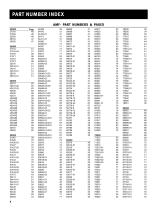
AMF- PART NUMBERS & PAGES 20000Page 21510 48
Open the catalog to page 3
PART NUMBER INDEX PRECISION GRID BASES 87293 87311-01 87312-01 87313-01 87314-01 87315-01 87321 87338 87338-01 87339 87339-01 87412 87456 87464 87477 87477-01 87478 87481 87483 87490 87491 87495 87496 87505 87505-01 87524 87541 87542 87542-01 87542-02 87542-03 87542-04 87543 87544 87552 87553 87571 87571-01 87571-02 87572 87572-01 87572-02 87575 87575-01 87576 87576-01 87581 87581-02 87581-03 87581-04 87581-05 87581-06 87581-07 87582 87583 87584 87587 87588 87589 87589-01 87590 87590-01 87593 87593-01 87593-02 87593-03 87593-04 87594 87595 Part NumberPage Part NumberPage C080822-16-50 17
Open the catalog to page 4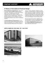
COMPANY HISTORY A History of Innovation & Practical Design Advanced Machine & Engineering Co. takes pride in its newly expanded AMROK® Modular Fixturing product line. Throughout our 40 year history of fixture design, we have created families of modular components which have made our product line your premiere source for modular fixturing. Thanks to our dedicated workforce and your feedback, we have found practical solutions to your common workholding problems. At Advanced Machine & Engineering Co., it is our policy to provide products and services that meet the needs and expectations of our customers...
Open the catalog to page 5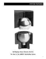
SYSTEM FEATURES Self-Aligning Fixture Elements (S.A.F.E.) The Heart of the AMROK® Workholding System 7
Open the catalog to page 6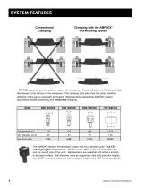
Conventional Clamping Clamping with the AMFLEX® Workholding System S.A.F.E. elements use ball pads to support the workpiece. These ball pads are flexible and align themselves to the contour of the workpiece. The clamping bars also have ball pads, therefore distortion of the part is practically eliminated. When properly applied, the AMROK® system guarantees flexible positioning and stress-free clamping. fThe AMROK® Modular Workholding System has four standard sizes “S.A.F.E.” self-aligning fixture elements. The four sizes differ by the diameter of the ball and the overall size of the units. Ball...
Open the catalog to page 7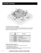
The System Features and Benefits “Horizontal Clamping” using the AMROK® Modular Workholding System. The shape of the workpiece and the machining operations to be performed will determine the style, location and number of components to be used. 1. Set Torque wrench to 32 ft. lbs = 5000 lbs. clamping force per clamp. 2. Total clamping force - 20,000 lbs. 3. Activate center Horizontal Clamp first. 4. Adjust AMF-51067 Ball Elements before activating remaining Horizontal Clamps. 5. Estimated time to assemble fixture = 15 minutes. CAD MODELS AVAILABLE BY CLICKING THE MODEL NUMBER Requires Internet...
Open the catalog to page 9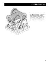
SYSTEM FEATURES The System Features & Benefits “Chain Clamping” using the AMROK® Modular Workholding System. The shape of the workpiece and the machining operations to be performed will determine the style, location and number of components to be used.
Open the catalog to page 10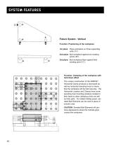
Fixture System - Vertical Function: Positioning of the workpiece 1st plane: Place workpiece on three supporting units (“A”). 2nd plane: Butt workpiece against two locating points (“B”). 3rd plane: Butt workpiece flush against third locating point (“C”). Function: Clamping of the workpiece with hold down effect The unique construction of the AMROK® Horizontal Clamp produces a downward as well as horizontal clamping force to insure that the workpiece will be held securely. The Horizontal Locators and Clamps have corresponding dual mounting positions located in their faces to allow clamping of thin...
Open the catalog to page 11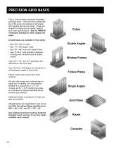
This is a list of some commonly requested grid base sizes. They are only a small sample of the sizes and shapes of grid plates and uprights that can be made. Sizes and shapes not listed can be readily made to your exact specifications. See our AMROK® Tombstone Catalog for other shapes and sizes. All grid bases are available in four styles: • Type “NH” with no holes. • Type “TH” with tapped holes. • Type “BT” with bored and tapped holes. • Type “S.A.F.E.” with precision hardened bushings and hardened-steel threaded inserts. Type “NH”, “TH”, and “BT” grid bases are described on the next page. Type...
Open the catalog to page 13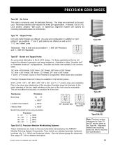
Type NH - No Holes This style is commonly used for dedicated fixturing. The holes are machined by the end user. Advanced Machine will machine the holes per specification. If desired, our S.A.F.E. Lock system, Jergens’ “Ball Lock”, or Speed-Loc alignment system are options for mounting dedicated plates on tombstones. Type TH - Tapped Holes Inch and metric threads are offered. Any size and configuration in addition to “grid patterns” are available. 1” and 2” grid patterns are offered as well as 3/4”, 1 1/2” and “offset” grids. Tolerances: Hole to hole non-accumulative = + .005” (for Precision) and...
Open the catalog to page 14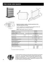
Machined workpiece quality is directly proportional to the individual tolerances involved. S.A.F.E. Grid Bases are manufactured to the highest precision and quality standards, with our Precision tolerances. NOTE: Please specify Cast Iron or Aluminum. * For Aluminum add 50% to these tolerances. Co-axial positioned bushings and inserts allow both positioning and clamping in every hole. The use of hardened precision bushings assures high wear resistance and replaceability. Glued-in bushings allow replacement without damage to the grid base or hole. If the insert is damaged, it too can usually be...
Open the catalog to page 15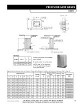
DETAILS: Custom grid bases are available upon request. Q Specify bushing I.D. used for system. NOTE: Add "A" for aluminum or "C for cast iron at the end of the part number. Note: Geometric tolerances shown are Precision. Please specify Standard or Precision and Cast Iron or Aluminum. Refer to Page 16. Subject to technical modifications. CA D MOD ELS AVA I LA BLE BY C LI CKIN G THE M O DE L NUMB ER Requires Internet access. CAD Models not available for part numbers shown in black.
Open the catalog to page 16All Advanced Machine & Engineering catalogs and technical brochures
 KTE40-1000
2 Pages
 P-SERIE
4 Pages
 F-SERIES
4 Pages
 B20 Dimensions Spring base
2 Pages
 F60 Dimensions, type KFHA
6 Pages
 Z10 Auto-Bleeder
3 Pages
 STB10 Rod Attachment STB
3 Pages
 M11 Dimensions MVA
1 Page
 KRM Safety Catcher
3 Pages
 Company Brochure
15 Pages
 F23 KFPD for torque
3 Pages
 Product Brochure
8 Pages
 TI-F50
6 Pages
 TI-S11
1 Page
 TI-B11
1 Page
 TI-A12
1 Page
 TI-A11
2 Pages
 TI-A10
7 Pages
 OppSystem-Section
24 Pages
 Accessories-Section
8 Pages
 tripoxyMINERAL
32 Pages
 aptoCLAMP
22 Pages
 microCLAMP
40 Pages
 triCENTRO
34 Pages
 powerCLAMP & 5axes powerCLAMP
90 Pages
 OTT - Worm Gears
162 Pages
 Shaft-Measurement
4 Pages
 Air-To-Electronic_Columns
4 Pages
 SPIETH Catalog
100 Pages
 SPEEDCUT
4 Pages
 AMLOCK_RLN Pneumatic Rodlock
16 Pages
 AMSAW Rail Saw Brochure
2 Pages
 AMSAW S-Series
6 Pages
 Amsaw P-Series
4 Pages
 AME Company Overview
20 Pages
 AMROK Workholding Solutions
23 Pages
 AMROK Tombstones
16 Pages


