- Catalogs
- Advanced Machine & Engineering
- AMBUSH Squeeze Bushings Catalog
AMBUSH Squeeze Bushings Catalog
1 /8Pages

AMBUSH Squeeze Bushings Catalog
1 /8Pages
Catalog excerpts

HYDRAULIC SQUEEZE BUSHINGS
Open the catalog to page 1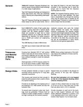
AMBUSH® Hydraulic Squeeze Bushings are used to clamp moving shafts to fixed housings in a wide range of applications. Type ASA Squeeze Bushings are designed to resist axial forces only. They are commonly used in fixturing and reciprocating shaft applications. Type AST Squeeze Bushings are designed to resist torque as well as axial forces. One or two holes (for dowel or roll pins) have been provided in the mounting cap to resist the torque and to insure that the Squeeze Bushing does not move. NOTE: The Squeeze Bushing clamps only to the shaft, not the outer diameter. The axial load is transmitted...
Open the catalog to page 2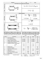
Axial Holding Force and Holding Torque Calculation Fa = d • (I - 2 • s ) • n • Phyd • m Sideload Calculations 0.75 *P»d ( 1.75*1+ C) Squeeze Bushings are not designed to take heavy sideloads. For this reason, auxiliary beanngs are offered for each size of Squeeze Bushing. The performance of a beanng is influenced by the conditions of speed, mating matenals. clearance, temperature, lubncation, type of loading etc. Of pnmary importance is the maintenance of an oil film between the beanng Surface to reduce (notion, dissipate heal and retard wear by minimizing metal to metal contact The most critical...
Open the catalog to page 3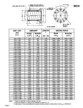
Notes: 1. Ream at assembly or drill for standard roll pins 2. Axial force based on 1,000 psi and coefficent of friction of .12 3. Side load at 1 inch axial distance to squeeze bushing, based on safety factor 3 and psurJ = 3000 Ibs/in?
Open the catalog to page 4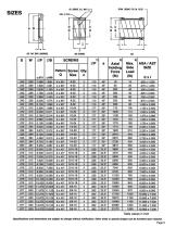
Specifications and dimensions are subject to change without notification. Other sizes or special shapes can be funished upon request. Page 5
Open the catalog to page 5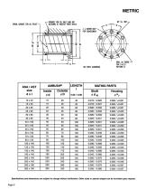
Specifcations and dimensions are subject to change without notification. Other sizes or special shapes can be furnished upon request.
Open the catalog to page 6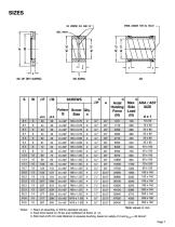
1. Ream at assembly, or drill for standard roll pins. 2. Axial force based on 70 bar and coefficient of fiction of .12. 3. Side load at 25 mm axial distance to squeeze bushing, based on safety of 3 and pSUf( = 20 N/mm2
Open the catalog to page 7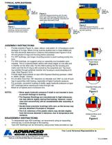
bushnc supm Figure 2 Type ASA Squeeze Bushing with (2) additional Type ASB bearings preloaded by (2) Type ASC caps with quadrings. Assembly will resist higher side loads of shaft. ASSEMBLY INSTRUCTIONS: 1. Provide chamfer (Figure 4), clean, deburr, and polish I.D. of housing to avoid damage of O-rings. When O-ring must be pushed over a cross-drilled port, the hole should be deburred or undercut and polished (see Figures 5 & 6). 2. Oil and grease O-rings and housing before assembly. 3. For AST bushings, use longer mounting screws to push bushing evenly into bore. 4. For ASA bushings, we suggest...
Open the catalog to page 8All Advanced Machine & Engineering catalogs and technical brochures
 KTE40-1000
2 Pages
 P-SERIE
4 Pages
 F-SERIES
4 Pages
 B20 Dimensions Spring base
2 Pages
 F60 Dimensions, type KFHA
6 Pages
 Z10 Auto-Bleeder
3 Pages
 STB10 Rod Attachment STB
3 Pages
 M11 Dimensions MVA
1 Page
 KRM Safety Catcher
3 Pages
 Company Brochure
15 Pages
 F23 KFPD for torque
3 Pages
 Product Brochure
8 Pages
 TI-F50
6 Pages
 TI-S11
1 Page
 TI-B11
1 Page
 TI-A12
1 Page
 TI-A11
2 Pages
 TI-A10
7 Pages
 OppSystem-Section
24 Pages
 Accessories-Section
8 Pages
 tripoxyMINERAL
32 Pages
 aptoCLAMP
22 Pages
 microCLAMP
40 Pages
 triCENTRO
34 Pages
 powerCLAMP & 5axes powerCLAMP
90 Pages
 OTT - Worm Gears
162 Pages
 Shaft-Measurement
4 Pages
 Air-To-Electronic_Columns
4 Pages
 SPIETH Catalog
100 Pages
 SPEEDCUT
4 Pages
 AMLOCK_RLN Pneumatic Rodlock
16 Pages
 AMSAW Rail Saw Brochure
2 Pages
 AMSAW S-Series
6 Pages
 Amsaw P-Series
4 Pages
 AME Company Overview
20 Pages
 AMROK Workholding Solutions
23 Pages
 AMROK Tombstones
16 Pages
 AMROCK Modular Workholding
80 Pages


