
- Catalogs
- Advanced Interconnections
- BGA Data Book


- Company
- Products
- Catalogs
- News & Trends
- Exhibitions
BGA Data Book

BGA Data Book
The document provides comprehensive information on the Micro-BGA Socketing System, focusing on the BGA Socket Adapter System, Flip-Top™ BGA Socket, and BGA Interposer. It covers applications in testing, development, validation, and production.
- Advanced screw-machined terminals with multi-finger contacts, gold-plated for superior connectivity.
- Compact design with a footprint only 2.00mm larger than the device.
- No need for external hold-downs, featuring unique alignment pins for protection and ease of placement.
- Protective covers for automated pick & place operations.
- Superior electrical performance with low signal attenuation.
- Terminals made from Brass-Copper Alloy (C36000).
- Contacts made from Beryllium Copper (C17200).
- Solder Ball options include lead-free and Tin/Lead compositions.
- Gold over Nickel plating for terminals and contacts.
- Available in 0.50mm and 0.65mm pitch.
- Standard Adapter and SMT Adapter options with FR-4 Fiberglass Epoxy Board material.
- Various alignment pin and packaging options like Tape and Reel.
- Superior electrical performance with differential insertion and return loss metrics.
- Insertion and extraction force averages at 35g and 30g per pin, respectively.
- Instructions on ordering, including options for terminal/contact plating, body type, and RoHS compliance.
- Extraction tools and additional accessories available separately.
- Custom adapters available for heat sink attachment.
- SMT Adapters for LGA to BGA conversion or SMT Board to Board applications.
- Closed bottom socket terminal for anti-wicking of solder.
- Online tools available for designing custom BGA Adapters or Sockets.
- Thousands of footprints available online for selection.
The document provides detailed technical specifications and highlights the advanced features, superior performance, and customization options of the BGA Socket Adapter Systems for various applications in electronics manufacturing.
The document includes a step-by-step guide on installing and using BGA sockets, including soldering the lower assembly to the PC board, attaching the upper assembly, and inserting the BGA device. It also describes using a heat sink actuator for device engagement.
The sockets are suitable for test, development, programming, and production applications across various industries, including medical, military, telecom, and automotive sectors. They offer solutions for transitioning to lead-free packages without redesigning PC boards.
The document references online tools such as the BGA Footprint Finder and Build-A-Part™ Product Configurator for designing and ordering custom parts. It also mentions the availability of detailed installation instructions and generic reflow profiles online.
Catalog excerpts

Test | Development | Validation | Production Micro-BGA Socketing System BGA Socket Adapter System Flip-Top™ BGA Socket BGA Interposer
Open the catalog to page 1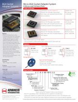
BGA Socket Adapter Systems Micro-BGA Socket Adapter System 0.50mm and 0.65mm Pitch Table of Models Section Title Description: Standard Adapter (A) Material: FR-4 Fiberglass Epoxy Board Note: Mates with Standard Socket for BGA device socketing. Description: SMT Adapter (A) Material: FR-4 Fiberglass Epoxy Board Note: Mates with Standard Socket for LGA Socketing or Board to Board applications. Features • Advanced’s field-proven screwmachined terminals with multi-finger contacts, arranged in an interstitial male/female pin pattern are gold plated for gold/gold interconnect. • Small overall size &...
Open the catalog to page 2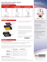
Adapter Systems Micro-BGA Socket Adapter System0.50mm and 0.65mm Pitch Standard TerminalsType -834 Note: Solder ball diameter is 0.012/(0.30mm) on 0.50mm pitch models and 0.014/(0.36mm) on 0.65mm pitch models. • Adapter matches footprint of BGA/LGA device and plugs into mating socket using unique male/female terminals in an interstitial pattern. • Socket matches footprint of BGA/LGA device. Use alignment pins to align Device/Adapter assembly during insertion into board-mounted Socket. • One extraction tool (P/N 8794) is supplied with each order. See page 15 for Generic Reflow Profiles. Design...
Open the catalog to page 3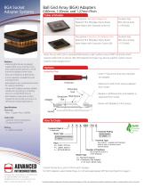
BGA Socket Adapter Systems Ball Grid Array (BGA) Adapters 0.80mm, 1.00mm, and 1.27mm Pitch Table of Models Description: Standard Adapter (A) Material: FR-4 Fiberglass Epoxy Board Note: Mates with Standard Socket (S) Description: Extraction Slot Adapter (AX) Material: FR-4 Fiberglass Epoxy Board Note: Mates with Extraction Socket (SB) Features • Soldering BGA Device to adapter subjects BGA to less thermal stress than soldering BGA directly to a PCB due to the adapter’s lower mass. • Uses same footprint as BGA device. • Custom adapters available for heat sink attachment. • Gold plated screw-machined...
Open the catalog to page 4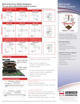
Ball Grid Array (BGA) Adapters For use with mating BGA Adapter Sockets Standard Terminals Consult factory for additional terminals. 0.80mm Pitch Type -700 Type -700 Tin/Lead: Type -720 Lead-free: Type -823 SMT (Surface Mount) BGA Socket Adapter Systems Tin/Lead: Type -737 Lead-free: Type -824 0.80mm pitch .020/(0.51) Dia. Solder Ball Tin/Lead: Type -736 Lead-free: Type -829 How It Works Device Adapter Reflow (solder) BGA device to adapter Reflow (solder) socket to PCB See page 15 for Generic Reflow Profiles. • Either Tin/Lead or Leadfree device packages can be attached to our RoHS Compliant Adapters....
Open the catalog to page 5
Adapter Systems Ball Grid Array (BGA) Adapter Sockets 0.80mm, 1.00mm, and 1.27mm Pitch Features • Advanced® exclusive solder ball terminals offer superior SMT processing. • Same footprint as BGA device. • Proven long-term performance in vigorous temperature cycling applications - solder ball terminal absorbs TCE mismatch. • Closed bottom socket terminal for 100% anti-wicking of solder. • Gold contacts allow gold/gold interconnections to Adapter pins. • Low insertion force socket with multi-finger high reliability Beryllium Copper contacts. • Coplanarity consistently under .006 inch industry standard. •...
Open the catalog to page 6
Ball Grid Array (BGA) Adapter Sockets BGA Socket Adapter Systems For use with mating BGA Adapters Standard Terminals Tin/Lead: Type -636 Lead-free: Type -819 Tin/Lead: Type -790 Lead-free: Type -788 Tin/Lead: Type -716 Lead-free: Type -816 Tin/Lead: Type -702 Lead-free: Type -828 Additional standard and custom terminals available. See Terminals section or consult factory. Reflow (solder) BGA device to adapter Reflow (solder) socket to PCB • Either Tin/Lead or Lead-free device packages can be attached to our RoHS Compliant Adapters. • PC boards can be processed with Tin/Lead BGA sockets in standard...
Open the catalog to page 7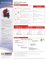
Flip-Top™ BGA Sockets 0.50mm Pitch Table of Models For Device Packages Up to 12 mm2 Description: SMT Standard (FRM) See Note 1 Note 1: See Application Spec. for recommended adhesive (epoxy) instructions. Description: SMT/Screw Mount (FRM) See Note 2 Height 0.68/(17.4mm)* approx. (*will vary based on reflow profile, paste volume, etc.) Note 2: Screws provided for additional strain relief when needed; reflow still required. Description: SMT Plus (FRM) Features • Model shown accommodates BGA packages up to 12mm sq. (22 x 22 rows) with larger sizes available upon request. • Precision machined spring...
Open the catalog to page 8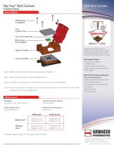
#0-80 Screws (4 supplied) Chip Support Plate Turn-screw Heat Sink BGA Device (not supplied) Design your own BGA Adapter or Socket using our online tools or submit your device mechanical specs and we will provide the matching part numbers. Upper Assembly Lower Assembly Step 1: Solder lower assembly to PC board, apply epoxy if required. Step 2: Attach upper assembly using four supplied screws. Step 3: Insert BGA device by hand or with the aid of a vacuum pen (recommended). Step 4: Place device-specific chip support plate (supplied) over device, close lid, and screw down heat sink actuator for device...
Open the catalog to page 9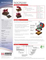
Flip-Top™ BGA Sockets 1.27mm and 1.00mm Pitch Table of Models Description: Socket (FRG, 1.27mm pitch) Material: Guide Box: Molded PPS Base: High Temp. Liquid Crystal Polymer (LCP) Description: Socket (FRH, 1.00mm pitch) Material: Guide Box: Molded PPS Base: FR-4 Glass Filled Epoxy Features • Designed to save space on new and existing PC boards in test, development, programming and production applications. • No external hold-downs or soldering of BGA device required. • AIC exclusive solder ball terminals offer superior processing. • Uses same footprint as BGA device. • Available with integral,...
Open the catalog to page 10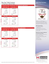
Terminals (for test, development and production applications) Thru-Hole_SMT (Surface Mount)_ _Thru-Hole_SMT (Surface Mount) 1.27mm pitch I .102 ^ (2.59) TT .206 (5.23) For details relating to proprietary information protected by patents, see Pat. www.advanced.com/patents. Specifications subject to change without notice. inch/(mm) Design your own BGA Adapter or Socket using our online tools or submit your device mechanical specs and we will provide the matching part numbers. BGA Footprint Finder • Thousands of footprints available online • Search by pitch, device size, etc. • Select matching image...
Open the catalog to page 11All Advanced Interconnections catalogs and technical brochures
 Application Note 2003-01
2 Pages
 Peel-A-Way® DIP Socket
2 Pages
 Molded DIP Socket
2 Pages
 Flip-Top™ Test Socket
2 Pages
 Test Point Pin
1 Page
 SOIC to DIP Adapters
1 Page
 B2B® SMT Connectors
2 Pages
 Mezza-pede® SMT Connectors
2 Pages
 Mod5 Series Flip-Top™
2 Pages
 Full Line Catalog
97 Pages


