
Catalog excerpts

LTspice IV Getting Started Guide Copyright © 2011 Linear Technology. All rights reserved.
Open the catalog to page 1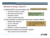
LTspice is also a great schematic capture ♦ Over 1100 macromodels of Linear Technology products ♦ 500+ SMPS Benefits of Using LTspice IV ♦ Stable SPICE circuit simulation with ♦ Unlimited number of nodes ♦ Schematic/symbol editor ♦ Waveform viewer ♦ Library of passive devices ♦ Fast simulation of switching mode power supplies (SMPS) ♦ Steady state detection ♦ Turn on transient ♦ Step response ♦ Efficiency / power computations ♦ Advanced analysis and simulation options ♦ Not covered in this presentation
Open the catalog to page 2
How Do You Get LTspice IV ♦ Go to http://www.linear.com/LTspice ♦ Left click on Download LTspice IV ♦ Register for a new MyLinear account to receive updates if you have not done so already
Open the catalog to page 3
Getting Started Copyright © 2011 Linear Technology. All rights reserved.
Open the catalog to page 4
Getting Started using LTspice IV ♦ Use one of the 100s of demo circuits available on linear.com ♦ Reviewed by Linear Technology's Factory Applications Group ♦ Use a pre-drafted test fixture (JIG) ♦ Provides a good starting point ♦ Use the schematic editor to create your own design ♦ LTspice contains macromodels for most LTC powerdevices
Open the catalog to page 5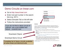
Demo Circuits on linear.com ♦ ♦ ♦ ♦ Go to http://www.linear.com Enter root part number in the search box (e.g. 3411) Select Simulate Tab on the left side Follow the instructions provided ORDER INFO Simulate If you do not find a demo circuit of interest, use a pre-drafted test fixture - covered next Download LTspice Download Demo Circuit LTspice IV is a powerful, fast and free simulation tool, schematic capture and waveform viewer with enhancements and models for improving the simulation of switching regulators. To download LTspice IV and other FREE simulation tools, please visit our Design...
Open the catalog to page 6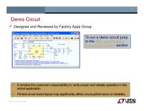
Demo Circuit Designed and Reviewed by Factory Apps Group To run a demo circuit jump to the Run and Probe a Circuit in LTspice section What if I cannot find a demo circuit? It remains the customer's responsibility to verify proper and reliable operation in the actual application Printed circuit board layout may significantly affect circuit performance or reliability © 2011 Linear Technology
Open the catalog to page 7
Getting Started using LTspice IV ♦ Use one of the 100s of demo circuits available on linear.com ♦ Reviewed by Linear Technology's Factory Applications Group ♦ Use a pre-drafted test fixture (JIG) ♦ Provides a good starting point ♦ Use the schematic editor to create your own design ♦ LTspice contains macromodels for most LTC powerdevices
Open the catalog to page 8
Pre-Drafted Test Fixture (JIG) ♦ Used for testing models during development ♦ Provides a draft starting point ♦ Not reviewed by Linear Technology’s factory applications team ♦ It remains the customer’s responsibility to verify proper and reliable operation in the actual application ♦ Printed circuit board layout may significantly affect circuit performance or reliability
Open the catalog to page 9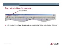
Start with a New Schematic New Schematic Left click on the New Schematic symbol in the Schematic Editor Toolbar
Open the catalog to page 10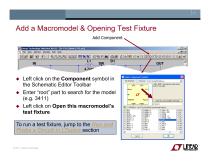
-1^ Fie View Wfndcw Emulate Help Add a Macromodel & Opening Test Fixture gjLinear Technology SwiteherCftP ill [SV 12V 35QmA 1313-asc] ♦ Left click on the Component symbol in the Schematic Editor Toolbar ♦ Enter “root” part to search for the model (e.g. 3411) ♦ Left click on Open this macromodel’s test fixture To run a test fixture, jump to the Ru Probe a Circuit in LTspice section
Open the catalog to page 11
Getting Started using LTspice IV ♦ Use one of the 100s of demo circuits available on linear.com ♦ Reviewed by Linear Technology's Factory Applications Group ♦ Use a pre-drafted test fixture (JIG) ♦ Provides a good starting point ♦ Use the schematic editor to create your own design ♦ LTspice contains macromodels for most LTC powerdevices
Open the catalog to page 12
Draft a Design Using the Schematic Editor Copyright © 2011 Linear Technology. All rights reserved.
Open the catalog to page 13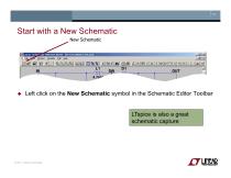
Start with a New Schematic New Schematic Left click on the New Schematic symbol in the Schematic Editor Toolbar LTspice is also a great schematic capture
Open the catalog to page 14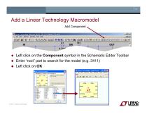
Add a Linear Technology Macromodel gjLinear Technology SwiteherCftP ill [SV 12V 35QmA 1313-asc] -1^ Fie View Wfndcw gmulete Help ♦ Left click on the Component symbol in the Schematic Editor Toolbar ♦ Enter “root” part to search for the model (e.g. 3411) ♦ Left click on OK
Open the catalog to page 15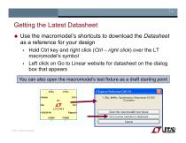
Getting the Latest Datasheet ♦ Use the macromodel’s shortcuts to download the Datasheet as a reference for your design ♦ Hold Ctrl key and right click (Ctrl - right click) over the LT macromodel’s symbol ♦ Left click on Go to Linear website for datasheet on the dialog box that appears You can also open the macromodel's test fixture as a draft starting point
Open the catalog to page 16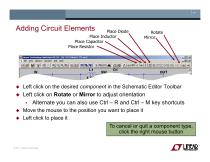
Adding Circuit Elements gj Linear Technology SwitcherCAP ID -[5V 12V 250mA 13T? a«] X. Ffe View Wrvkw SjnUete £d* Help ♦ Left click on the desired component in the Schematic Editor Toolbar ♦ Left click on Rotate or Mirror to adjust orientation ♦ Alternate you can also use Ctrl - R and Ctrl - M key shortcuts ♦ Move the mouse to the position you want to place it ♦ Left click to place it To cancel or quit a component type, click the right mouse button
Open the catalog to page 17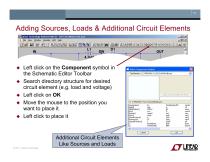
Adding Sources, Loads & Additional Circuit Elements gj Linear Technology EwitcherCAD II] - [5V 12V 250mA 1377 act] Rfe View Wfnjgw SjmOate &*, Help Left click on the Component symbol in the Schematic Editor Toolbar Search directory structure for desired circuit element (e.g. load and voltage) Left click on OK Move the mouse to the position you want to place it Left click to place it Additional Circuit Elements Like Sources and Loads Select Component Symbol!
Open the catalog to page 18
Highlights of Additional Circuit Elements ♦ Left click on the Component symbol in directory of additional circuit elements: ♦ Arbitrary behavioral source ♦ Voltage dependent voltage ♦ Current dependent current ♦ Voltage dependent current ♦ Current dependent voltage ♦ Independent current source ♦ JFET transistor ♦ Mutual inductance ♦ MOSFET transistor the Schematic Editor Toolbar for a Lossy transmission line Bipolar transistor Voltage controlled switch Lossless transmission line Uniform RC-line Independent voltage source Current controlled switch Subcircuit MESFET transistor ...many more
Open the catalog to page 19All ADI catalogs and technical brochures
-
LTC2068
30 Pages
-
LTC6373
34 Pages
-
ADL9006
16 Pages
-
ADL8104
23 Pages
-
AD4115
52 Pages
-
ADUM7702
22 Pages
-
AD7383
33 Pages
-
AD7384
33 Pages
-
AD4114
49 Pages
-
ADUM7704
22 Pages
-
AD7134
86 Pages
-
New Products Catalog
43 Pages
-
RF/IF Amplifiers
9 Pages
-
SAR ADC Drivers
2 Pages
-
SmartMesh Brochure
8 Pages
-
INDUSTRIAL SIGNAL CHAIN
24 Pages
-
AUTOMOTIVE ELECTRONIC SOLUTIONS
48 Pages
-
Battery Management Solutions
32 Pages
-
DC/DC uModule Power Products
32 Pages
-
Wireless & RF Solution
36 Pages
-
LT6656 - 1
18 Pages
Archived catalogs
-
New Products Catalog
39 Pages
-
Power Management for LEDs
24 Pages
-
High Speed ADC Products Brochure
14 Pages


