
Catalog excerpts

LT1999-10/LT1999-20/ LT1999-50 1 1999fa TYPICAL APPLICATION FEATURES DESCRIPTION High Voltage, Bidirectional Current Sense Amplifier The LT®1999 is a high speed precision current sense amplifier, designed to monitor bidirectional currents over a wide common mode range. The LT1999 is offered in three gain options: 10V/V, 20V/V, and 50V/V. The LT1999 senses current via an external resistive shunt and generates an output voltage, indicating both magnitude and direction of the sensed current. The output voltage is referenced halfway between the supply voltage and ground, or an external voltage can be used to set the reference level. With a 2MHz bandwidth and a common mode input range of –5V to 80V, the LT1999 is suitable for monitoring currents in H-Bridge motor controls, switching power supplies, solenoid currents, and battery charge currents from full charge to depletion. The LT1999 operates from an independent 5V supply and draws 1.55mA. A shutdown mode is provided for minimizing power consumption. The LT1999 is available in an 8-lead MSOP or SOP package. L, LT, LTC, LTM, Linear Technology and the Linear logo are registered trademarks of Linear Technology Corporation. All other trademarks are the property of their respective owners. APPLICATIONS n Buffered Output with 3 Gain Options: 10V/V, 20V/V, 50V/V n Gain Accuracy: 0.5% Max n Input Common Mode Voltage Range: –5V to 80V n AC CMRR > 80dB at 100kHz n Input Offset Voltage: 1.5mV Max n –3dB Bandwidth: 2MHz n Smooth, Continuous Operation Over Entire Common Mode Range n 4kV HBM Tolerant and 1kV CDM Tolerant n Low Power Shutdown <10ìA n –55°C to 150°C Operating Temperature Range n 8-Lead MSOP and 8-Lead SO (Narrow) Packages n High Side or Low Side Current Sensing n H-Bridge Motor Control n Solenoid Current Sense n High Voltage Data Acquisition n PWM Control Loops n Fuse/MOSFET Monitoring Full Bridge Armature Current Monitor TIME (10ìs/DIV) 2.5V VOUT (2V/DIV) V+IN (20V/DIV) 1999 TA01b VOUT V+IN LT1999 4k 0.8k 160k 160k 2ìA 4k 0.8k SHDN 5V V+ V+ 5V V+ RS 1999 TA01a + – + – VS 1 8 2 3 4 7 6 5 0.1ìF 0.1ìF VOUT RG V+IN V–IN VREF VSHDN V+ V+
Open the catalog to page 1
LT1999-10/LT1999-20/ LT1999-50 3 1999fa ELECTRICAL CHARACTERISTICSThe l denotes the specifications which apply over the full operating temperature range, 0°C < TA < 70°C for C-grade parts, –40°C < TA < 85°C for I-grade parts, and –40°C < TA < 125°C for H-grade parts, otherwise specifications are at TA = 25°C. V+ = 5V, GND = 0V, VCM = 12V, VREF = floating, VSHDN = floating, unless otherwise specified. See Figure 2. LEAD FREE FINISH TAPE AND REEL PART MARKING* PACKAGE DESCRIPTION SPECIFIED TEMPERATURE RANGE LT1999CS8-20#PBF LT1999CS8-20#TRPBF 199920 8-Lead Plastic SO 0°C to 70°C...
Open the catalog to page 3
LT1999-10/LT1999-20/ LT1999-50 4 1999fa E LECTRICAL CHARACTERISTICSThe l denotes the specifications which apply over the full operating temperature range, 0°C < TA < 70°C for C-grade parts, –40°C < TA < 85°C for I-grade parts, and –40°C < TA < 125°C for H-grade parts, otherwise specifications are at TA = 25°C. V+ = 5V, GND = 0V, VCM = 12V, VREF = floating, VSHDN = floating, unless otherwise specified. See Figure 2. SYMBOL PARAMETER CONDITIONS MIN TYP MAX UNITS CMRR Sense Input Common Mode Rejection VCM = –5V to 80V VCM = –5V to 5.5V VCM = 12V, 7VP-P, f = 100kHz, VCM = 0V, 7VP-P, f = 100kHz...
Open the catalog to page 4
LT1999-10/LT1999-20/ LT1999-50 5 1999fa E LECTRICAL CHARACTERISTICSThe l denotes the specifications which apply over the full operating temperature range, –55°C < TA < 150°C for MP-grade parts, otherwise specifications are at TA = 25°C. V+ = 5V, GND = 0V, VCM = 12V, VREF = floating, VSHDN = floating, unless otherwise specified. See Figure 2. SYMBOL PARAMETER CONDITIONS MIN TYP MAX UNITS VSENSE Full-Scale Input Sense Voltage (Note 7) VSENSE = V+IN – V–IN LT1999-10 LT1999-20 LT1999-50 l l l –0.35 –0.2 –0.08 0.35 0.2 0.08 V V V VCM CM Input Voltage Range l –5 80 V RIN(DIFF) Differential Input...
Open the catalog to page 5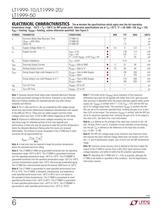
LT1999-10/LT1999-20/ LT1999-50 6 1999fa ELECTRICAL CHARACTERISTICS Note 1: Stresses beyond those listed under Absolute Maximum Ratings may cause permanent damage to the device. Exposure to any Absolute Maximum Rating condition for extended periods may affect device reliability and lifetime. Note 2: Pin 2 (+IN) and Pin 3 (–IN) are protected by ESD voltage clamps which have asymmetric bidirectional breakdown characteristics with respect to the GND pin (Pin 5). These pins can safely support common mode voltages which vary from –5.25V to 88V without triggering an ESD clamp. Note 3: Exposure to...
Open the catalog to page 6
LT1999-10/LT1999-20/ LT1999-50 10 1999fa LT1999-10 Common Mode Rising Edge Step Response VOUT (0.5V/DIV) VCM (25V/DIV) TIME (0.5ìs/DIV) 1999 G25 VCM, tRISE 20ns VOUT LT1999-10 Common Mode Falling Edge Step Response VOUT (0.5V/DIV) VCM (25V/DIV) TIME (0.5ìs/DIV) 1999 G26 VCM, tFALL 20ns VOUT VOUT (0.5V/DIV) VCM (25V/DIV) TIME (0.5ìs/DIV) 1999 G27 VCM, tRISE 20ns VOUT LT1999-20 Common Mode Rising Edge Step Response LT1999-20 Common Mode Falling Edge Step Response VOUT (0.5V/DIV) VCM (25V/DIV) TIME (0.5ìs/DIV) 1999 G28 VCM, tFALL 20ns VOUT TYPICAL PERFORMANCE CHARACTERISTICS LT1999-50 Common...
Open the catalog to page 10
LT1999-10/LT1999-20/ LT1999-50 12 1999fa PIN FUNCTIONS V+ (Pins 1, 4): Power Supply Voltage. Pins 1 and 4 are tied internally together. The specified range of operation is 4.5V to 5.5V, but lower supply voltages (down to approximately 4V) is possible although the LT1999 is not tested or characterized below 4.5V. See the Applications Information section. +IN (Pin 2): Positive Sense Input Pin. –IN (Pin 3): Negative Sense Input Pin. GND (Pin 5): Ground Pin. REF (Pin 6): Reference Pin Input. The REF pin sets the output common mode level and is set halfway between V+ and GND using a divider made...
Open the catalog to page 12All ADI catalogs and technical brochures
-
 LTC2068
30 Pages
-
 LTC6373
34 Pages
-
 ADL9006
16 Pages
-
 ADL8104
23 Pages
-
 AD4115
52 Pages
-
 ADUM7702
22 Pages
-
 AD7383
33 Pages
-
 AD7384
33 Pages
-
 AD4114
49 Pages
-
 ADUM7704
22 Pages
-
 AD7134
86 Pages
-
 LTspice IV
53 Pages
-
 New Products Catalog
43 Pages
-
 RF/IF Amplifiers
9 Pages
-
 SAR ADC Drivers
2 Pages
-
 SmartMesh Brochure
8 Pages
-
 INDUSTRIAL SIGNAL CHAIN
24 Pages
-
 AUTOMOTIVE ELECTRONIC SOLUTIONS
48 Pages
-
 Battery Management Solutions
32 Pages
-
 DC/DC uModule Power Products
32 Pages
-
 Wireless & RF Solution
36 Pages
-
 LT6656 - 1
18 Pages


Archived catalogs
-
 New Products Catalog
39 Pages
-
 Power Management for LEDs
24 Pages
-
 High Speed ADC Products Brochure
14 Pages


