
- Catalogs
- ADFweb.com
- HD67001

HD67001

HD67001
- Power Supply: Connector1 is used for power supply with V- as Ground and V+ as Positive wire, supporting 12/18 VAC – 4 VA or 12/24 VDC – 4 Watt.
- CANopen Termination: Jumper1 allows termination of the CANopen line with options for open or 120 ohm.
- Modbus Connection: Connector3 is for Modbus on RS485 with S as Shield, B as Negative wire, and A as Positive wire. Jumper2 provides termination for the Modbus line with options for open or 220 ohm.
- CANopen Connection: Connector2 includes H for High wire, S for Shield, and L for Low wire.
- RS232 Port: The D-SUB9-Male port is used for programming and Modbus on RS232, with specific pin assignments for TX, RX, and GND.
- Boot Mode: Jumper3 allows switching between Boot Mode and Normal Mode.
- LED Indicators: Three green LEDs (Led1, Led2, Led3) are used for status indication.
Catalog excerpts
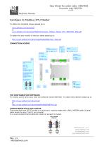
Box Sheet for order code: HD67001 Document code: BS67001 V1.002 Electronic Devices CanOpen to Modbus RTU Master To obtain the complete manual please go to www.adfweb.com/download or www.adfweb.com/download/filefold/Canopen_Modbus_Master_RTU_MN67001_ENG.pdf To obtain the new version of this box sheet please go to http://www.adfweb.com/download/filefold/BS67001_ENG.pdf CONNECTION SCHEME Connector2: CANopen Jumper1: Termination CANopen Line = Open H = High wire S = Shield L = Low wire V- = Ground V+ = Positive wire Led3: Green Jumper2: Termination Modbus Line S = Shield B = Negative wire A = Positive wire PIN2 = TX PIN3 = RX PIN5 = GND Used for: A) Programmation Port B) Modbus on RS232 To connect the device to the COM port of a PC in order to set it. You have to use the programming cable AC34107. Or a cable made as showed here: Jumper3: Boot mode = Yes Jumper Boot Mode = No Jumper Normal Mode THE CONFIGURATION SOFTWARE: For setting up the device you need the software named SW67001. To obtain this software please go to http://www.adfweb.com/download or http://www.adfweb.com/download/filefold/SW67001.zip CHARACTERISTICS OF THE CABLES: The connection from RS232 socket to a serial port must be made with a NULL MODEM cable (a serial cable where the pins 2 and 3 are crossed). It is recommended that the RS232C Cable not exceed 15 meters. NULL MODEM CABLING ADFweb.com s.r.l. www.adfweb.com [email protected] support@adfweb.
Open the catalog to page 1All ADFweb.com catalogs and technical brochures


- Data logger
- Wireless datalogger
- Datalogger without display
- DIN rail converter
- Ethernet converter
- Serial converter
- RS-232 converter
- RS-485 converter
- Power converter
- Fiber optics converter
- Ethernet datalogger
- Modbus datalogger
- Modbus RTU converter
- Modbus converter
- CANbus converter
- GSM modem
- DIN rail modem
- Robust converter
- Alarm modem
- DIN rail data-logger