- Catalogs
- ADELSYSTEM
- CB122410A
- Company
- Products
- Catalogs
- News & Trends
- Exhibitions
CB122410A
1 /1Page

CB122410A
1 /1Page
Catalog excerpts

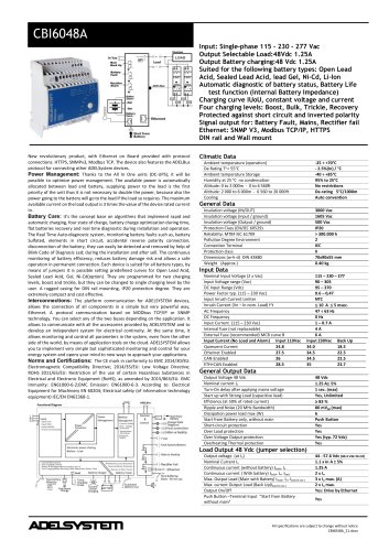
Input: Single-phase 115 – 230 - 277 Vac Output Selectable Load: 12 Vdc 15A; 24 Vdc 10A Output Battery charging: 12 Vdc 15A; 24 Vdc 10A Suited for the following battery types: Open Lead Acid, Sealed Lead Acid, lead Gel and Ni-Cd Automatic diagnostic of battery status, Battery Life Test function (internal Battery Impedance) Charging curve IUoU, constant voltage and current Four charging levels: Boost, Absorption, Float, Recovery Protected against short circuit and inverted polarity Signal output: for battery Fault, Mains or Back-UP Modbus RTU for all parameter battery and system Protection degree IP20; Space saving General Output Data Technical features Power Management: Thanks to the All In One units (DC-UPS), it will be possible to optimize power management. The available power is automatically allocated between load and battery, supplying power to the load is the first priority of the unit thus it is not necessary to double the power, because also the power going to the battery will go to the load if the load so requires. The maximum available current on the load output is 3 times the value of the device rated current In. Battery Cater: it’s the concept base on algorithms that implement rapid and automatic charging, four state of charge, battery charge optimization during time, flat batteries recovery and real time diagnostic during installation and operation. The Real Time Auto-diagnostic system, monitoring battery faults such as, battery Sulfated, elements in short circuit, accidental reverse polarity connection, disconnection of the battery, they can easily be detected and removed by help of Blink Code of Diagnosis Led; during the installation and after sell. The continuous monitoring of battery efficiency, reduces battery damage risk and allows a safe operation in permanent connection. Each device is suited for all battery types, by means of jumpers it is possible setting predefined curves for Open Lead Acid, Sealed Lead Acid, Gel, Ni-Cd(option). They are programmed for two charging levels, boost and float, but they can be changed to single charging level by the user. A rugged casing for DIN rail mounting, IP20 protection degree. They are extremely compact and costeffective. Interconnections: The platform communication for ADELSYSTEM devices allows the connection of all components in a simple but very powerful way. A protocol communication based on Modbus RTU. You can select any of the two buses depending on the application. It allows to communicate with all the accessories provided by ADELSYSTEM and to develop an independent system for electrical continuity. At the same time, it allows monitoring and control all parameters in the system, even from the other side of the world, by means of application tools on the cloud. ADELSYSTEM allows you to implement very simple but sophisticated monitoring and control for your energy system and opens your mind to new ways to approach your applications. Norms and Certifications In Conformity to: EN60950 / UL60950-1 and CSA C22.2 No. 60950-1-07 (Information Technology Equipment Safety Part1: Safety EN IEC 62368-1: 2014/AC:2015; EN54-4 Fire Detection and fire alarm systems; 89/336/EEC EMC Directive; 2014/35/UE (Low Voltage); DIN41773 (Charging cycle); Emission: IEC 61000-6-4; Immunity: IEC 61000-6-2. CE. Climatic Data Ambient temperature (operation) De Rating Ta > 50°C Ambient temperature Storage Humidity at 25 °C no condensation Cooling General Data Insulation voltage (IN/OUT) Insulation voltage (input / ground) Insulation voltage (Output / ground) Protection Class (EN/IEC 60529) Reliability: MTBF IEC 61709 Pollution Degree Environment Connection Terminal Blocks screw Type Connection Terminal Protection class (PE Connected) Dimensions (w-h-d) (Approx.) Weight (Approx.) Input Data Nominal Input Voltage (2 x Vac) Input Voltage range (Vac) Inrush Current (Vn – In nom. Load) I2t Frequency Input Current (115 – 230 Vac) Internal fuse (not replaceable) External Fuse (recommended) MCB curve B Select Output Voltage 12 or 24 Vdc. By: Turn-On delay after applying mains voltage Start up with Strong Load (capacitive load) Efficiency (at 50% of rated current) Dissipation power load max (W) Continuous current (without battery) Iload= In Continuous current (With battery) Iload= In+ Ibatt Max. current Output Load (Main) Iload (4 sec.) Max. current Output Load (Back Up)Iload (4 sec.) Push Button or Remote Input Control (RTCONN cable) Time Buffering; min (switch output off without main input) Short-circuit protection Over Load protection Over Voltage Output protection Overheating Thermal protection Jumper Enabling 1 sec. (max) Yes, Unlimited 91 % 28 In 2 x In 3 x In max. 2 x In max. Start From Battery Without Main 0.5;2;5;10;15; 20; 30; 45;60;∞ Yes Yes Yes (typ. 35 Vdc) Yes Load Output 24 Vdc (jumper selection) Output voltage (at In) Nominal current In = Iload Threshold alarm Battery almost flat Protections against total discharge Load Output 12 Vdc (jumper selection) Output voltage (at In) Nominal current In = Iload Threshold alarm Battery almost flat Protections against total discharge Battery Output Output Voltage Battery Boost charge (25 °C) (at In) Max. time Boost Charge Min. time Boost Charge Jumper Configuration battery type (V cell) Ni-Cd (optional); when Float Charging mode Charging current max Ibatt Charging current limiting Iadj Reverse battery protection Sulfated battery check Detection of element in short circuit Quiescent Current on the battery Charging Curve automatic: IUoU Remote Input Control (RTCONN cable) Follow Out Load 2.4 V/cell. 15 h 1 min. 2.23;2.25;2.27;2.3; NiCd:1.5 (20 cell.) In 5% 10 ÷ 100 % / Ibat Yes Yes (by Jumper) Yes 100 mA 4 stages Boost /Float Signal Output (free switch contacts) Main or Backup Power Low Battery Fault Battery Type of Signal Output Contact Max. Current can be switched (EN60947.4.1): Max. DC1: 30 Vdc 1 A; AC1: 60 Vac 1A Min.1mA at 5 Vdc Resistive load Min permissive load Signal Input / Output (RJ45) Temp. Comp. Battery (with external probe) Modbus RTU Modbus RTU
Open the catalog to page 1All ADELSYSTEM catalogs and technical brochures
 CBI6048A
2 Pages
 CBI2501224A
2 Pages
 DFX60110
1 Page
 BAT12Wh
2 Pages
 DFX1524A
1 Page
 DFX1512A
1 Page
 DFX6012A
1 Page
 DFX6024A
1 Page
 CBI6024A
1 Page
 CBI6012A
1 Page
 CB6024A
1 Page
 CB6012A
1 Page
 FLEX50048A
1 Page
 FLEX28048A
1 Page
 FLEX17048A
1 Page
 FLEX28012A
1 Page
 FLEX17012A
1 Page
 FLEX6012A
1 Page
 FLEX28024B
1 Page
 FLEX50024B
1 Page
 FLEX17024B
1 Page
 FLEX9024B
1 Page
 FLEX50024A
1 Page
 FLEX28024A
1 Page
 FLEX17024A
1 Page
 FLEX9024A
1 Page
 FLEX6024A
1 Page
 DPY353
1 Page
 DPY351
2 Pages
 MRF102
1 Page
 DC-UPS Catalogue
12 Pages
 POWER SUPPLY FLEX Catalogue
2 Pages
 BATTERY HOLDER 12V
2 Pages
 CB2420A
1 Page
 CB2410AC
1 Page
 CB1235A
1 Page
 CB243A
1 Page
 CB304A
1 Page
 CB363A
1 Page
 CB123A/48
1 Page
 CB1210A
1 Page
 CB123A
1 Page
 CB12245AJ
1 Page
 CB12245A
1 Page
 BAT12VRLA
1 Page
 BAT7.2VRLA
1 Page
 BAT3.4VRLA
1 Page
 BAT1.2VRLA
1 Page
 CBI2801224A
2 Pages
 CBI4810A
1 Page
 CBI2420AP
1 Page
 CBI2420A
1 Page
 CBI1235A
1 Page
 CBI485A
1 Page
 CBI2410A
1 Page
 CBI245A
1 Page
 CBI243A
1 Page
 CBI1210A
1 Page
 CBI126A
1 Page
 CBI123A
1 Page


- LIMING power supply
- LIMING DC power supply
- Display module
- LIMING AC/DC power supply
- LCD display panel
- Industrial display panel
- TFT display module
- CE power supply
- Single-output power supply
- Switching power supply
- Power supply for industrial applications
- Color display panel
- Circuit breaker
- LED display panel
- LIMING battery charger
- LIMING power supply with overload protection
- Compact power supply
- Electronic display panel
- LIMING DIN rail power supply
- Backlit display panel