


- Company
- Products
- Catalogs
- News & Trends
- Exhibitions
A3800 Step by Step
A3800 Step by Step
Catalog excerpts
Vibration Monitoring System MASTER LANGUAGE
Open the catalog to page 1
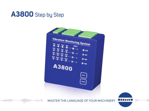
A3800 - Vibration Monitoring System The A3800 unit is the compact size on-line monitoring and diagnostic system. It is designed to increase machine reliability. The small size of the A3800 enables to mount it directly on the DIN rail. The optional number of channels (4, 8, 12, 16) is available on the A3800 unit. The same number of AC and DC channels are always available. The 4 tacho sensors can be used in 16 channel option. The number of channels is determined by the license file. When the user wants to increase the number of channels, then only the new license file is written to unit memory....
Open the catalog to page 3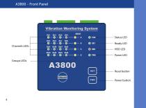
Vibration Monitoring System Channels LEDs Groups LEDs A3800 Status LED Ready LED HDD LED Power LED Reset button Power button
Open the catalog to page 4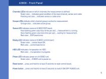
A3800 - Front Panel Channels LEDs indicate on which channels the measurement is defined. Green color … indicates good condition of the input channel, sensor and cable. Flashing red color … indicates sensor or cable error. Groups LEDs indicate which channel group is active for measurement. Orange color … indicates active group. Status LED indicates status of A3800 DSP board. Fast flashing green color (four times per sec) … measurement is running. Slow flashing green color (one time per sec) … waiting for measurement. Red color … DSP board error. Ready LED indicates status of A3800 control board....
Open the catalog to page 5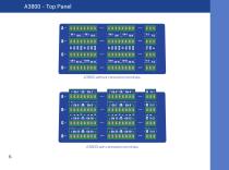
A3800 with connection terminals
Open the catalog to page 6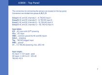
A3800 - Top Panel The connectors for connecting the sensors are located on the top panel. Connectors are divided into groups A, B, C, D. Group A: AC and DC channels 1 – 4, TACHO input 1. Group B: AC and DC channels 5 – 8, TACHO input 2. Group C: AC and DC channels 9 – 12, TACHO input 3. Group D: AC and DC channels 13 – 16, TACHO input 4. Input labels: ICP ... AC input with ICP® powering DCa ... DC input GND ... common ground for AC and DC inputs SHLD ... shielding Trig ... TACHO (trigger) input GND ... ground V+ ... 5 V TACHO powering, max. 250 mA Input ranges: AC input: +/-12 V peak - peak DC...
Open the catalog to page 7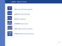
WiFi: input for WiFi antenna (optional). AUDIO I/O: 3.5 jack audio socket. ETHERNET: Ethernet socket. HDMI: HDMI port (monitor connection). POWER: socked for 12-24 V DC powering.
Open the catalog to page 9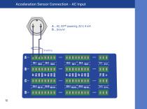
Acceleration Sensor Connection - AC Input A ... AC, ICP® powering, 22 V, 4 mA B ... Ground
Open the catalog to page 10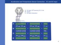
Acceleration and Temperature Sensor Connection - AC and DC Input A ... AC signal, ICP® powering, 22 V, 4 mA B ... Ground C ... DC signal, temperature
Open the catalog to page 11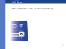
Power Supply The A3800 unit is powered by DC voltage 12 - 24 V. Power consumption is max. 10 W.
Open the catalog to page 13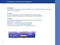
Connection to the Computer Network Serial Number: Each A3800 unit has a unique 6-digit serial number. This serial number is used for creation of the unit name and its IP address. Unit Name: This is the name under which the unit is displayed in the computer network. Initially it is “A3800-”Serial Number. For the unit below it is “A3800-628905”. IP Address: Is a numerical label assigned to each device connected to a computer network. The IP address is initially set to: 192.168.1.2xx ... for unit serial number ending by 00-09, 192.168.1.1xx ... for unit serial number ending by 10-99. IP address...
Open the catalog to page 14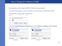
You will probably need to change the A3800’s IP address for proper operation. 1. Use the Ethernet cable and connect the A3800 unit with PC directly or through network (switch). 2. Press Win + R. Type “mstsc” and press Enter. 3. New window Remote Desktop Connection appears. Enter Unit Name or IP Address and press Connect. Unit Name
Open the catalog to page 15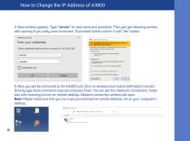
4. New window appears. Type “remote” for user name and password. Then you get following window with warning if you really want to connect. To proceed further confirm it with ‘Yes’ button. 5. Now you will be connected to the A3800 unit. Click on windows start button (left bottom corner). Directly type there command ncpa.cpl and press Enter. You can get this ‘Network connections’ folder also with choosing an icon on remote desktop. Network connection window will open. Note: Please make sure that you run ncpa.cpl command on remote desktop, not on your computer’s d
Open the catalog to page 16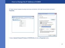
6. Select network adapter (usually Local area connection), click right mouse button and select Properties. 7. Select Internet Protocol IP Version 4 (TCP/IPv4) and click on Properties button.
Open the catalog to page 17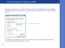
8. New window appears. You can change IP address of A3800 unit on General tab in the box IP address. After this change you have to create the new remote connection (connection with old IP address will stop working). The A3800 unit’s IP address has to be in the same subnet as your PC. Contact your IT department in order to get IP address according to your network. 18
Open the catalog to page 18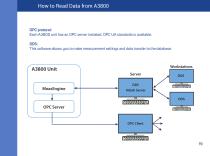
How to Read Data from A3800 OPC protocol: Each A3800 unit has an OPC server installed. OPC UA standards is available. DDS: This software allows you to make measurement settings and data transfer to the database.
Open the catalog to page 19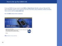
To set up A3800 unit you need to install DDS and Adash Server (MySQL) software. Microsoft SQL Server database system is also supported. For more information about installation of DDS and Adash Server visit our web site www.adash.com. Run the DDS software after installation. DDS software startup window.
Open the catalog to page 20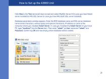
Click New in the Tree tab (small down arrow) and select MySQL Server 8 (in case you have Adash server installed) or MS SQL Server (in case you have Microsoft SQL server installed). Database parameters window appears. Enter the DDS database name and SQL server database name (small characters, without space and special characters), IP address or name of the computer where you installed Adash Server. In case you installed the Adash Server on your local PC, type “localhost” into the Server item. Then enter “adash” as User name and “adash” as a Password. Confirm by OK and new empty online database...
Open the catalog to page 21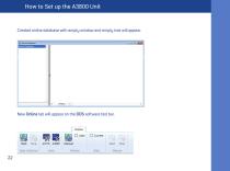
Created online database with empty window and empty tree will appear. New Online tab will appear on the DDS software tool bar.
Open the catalog to page 22All Adash catalogs and technical brochures
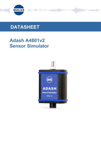 Adash A4801v2 Sensor Simulator
2 Pages
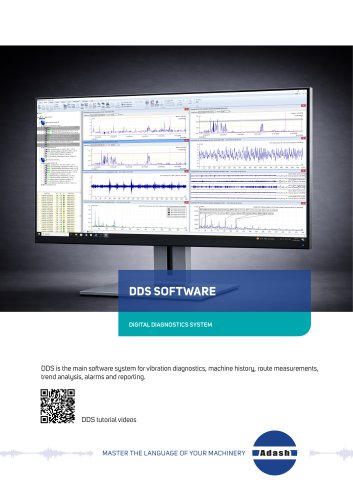 DDS
4 Pages
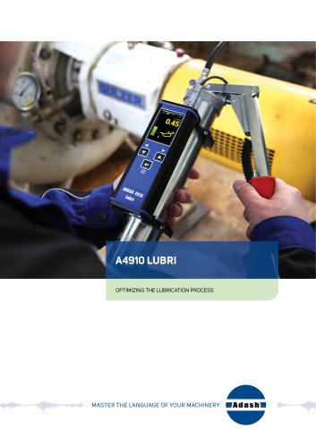 A4910 Lubri
4 Pages
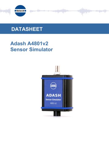 A4801 v2 Sensor Simulator
2 Pages
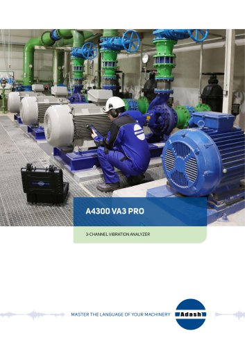 A4300 VA3 Pro
3 Pages
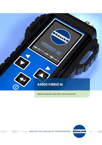 A4900 Vibrio M
3 Pages
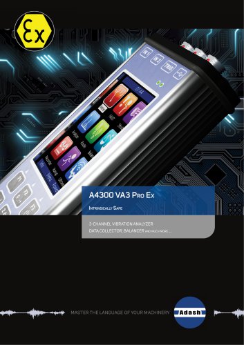 A4300 VA3 Pro Ex
4 Pages
 Adash Brochure
17 Pages
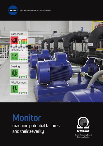 Omega_Data_sheet
4 Pages
 A4404 SAB
4 Pages
 A4900 - Vibrio M Ex
4 Pages
 VA5 Pro
3 Pages
 A3716
3 Pages
Archived catalogs
 A3800
4 Pages
 A4910 Lubri
4 Pages
 Omega_manual
32 Pages
- Analysis software solution
- Process software
- Cloud-based software
- Monitoring software solution
- Measurement software
- Machine software
- Condition monitoring module
- Digital monitoring module
- Storage software
- Adash vibration meter
- Vibration sensor
- Online monitoring module
- Benchtop monitoring system
- Alarm software
- Vibration monitoring device
- Compact monitoring module
- Data acquisition monitoring module
- Machine monitoring module
- Mechanical software
- Adash portable vibration meter