

SPIDER
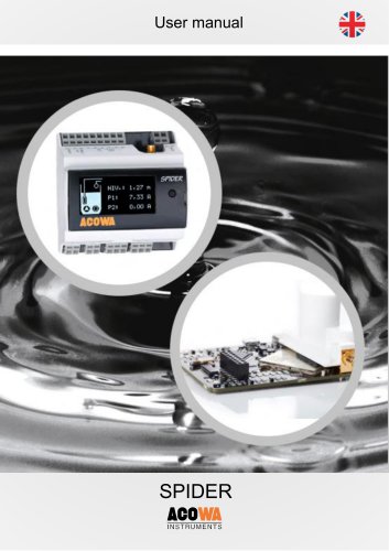
SPIDER
SPIDER is a robust control system developed in Denmark for pump control, data collection, alarm management, and groundwater lowering, suitable for harsh environments.
- Advanced pump control with alternation and emergency functions.
- Includes GSM/GPRS modem and supports Modbus RTU/TCP & COMLI protocols.
- Compatible with 2.4” OLED and 7” color touch displays.
- Features flow calculation and pump service indication.
- Equipped with a power bank for power failure scenarios.
Requires a 230 VAC power supply, mountable on a 35mm DIN-rail, operational between -20°C to +50°C, and should avoid direct sunlight exposure.
- Voltage: 230 VAC +10% / -20%
- Frequency: 50/60Hz
- Consumption: Max 10W
- Analog Input: 0-20mA / 4-20mA, non-isolated.
- Digital Inputs: 6, usable as 0-10V analog inputs.
- Digital Outputs: 4 relay outputs, electrically isolated.
Features a red button for emergency control and status indication diodes. Supports external units and ModBus communication.
Supports 2.4” OLED and 7” EAGLE HMI displays with specific installation instructions.
Allows SPIDER configuration via USB or TCP, featuring a user interface with function buttons and settings selection.
- Pump control and flow interface.
- Groundwater lowering and monitoring.
- Compressor and concertor control.
Includes advanced functions like high-level switch version 2 and pump control using only level switch.
Relay NO #11 and #21 support up to 10 A at 230Vac, while NO #31 and #41 support up to 2 A at 230Vac, with specific current and switch speed parameters.
Features a red button for reset and interface functions, with specific activation sequences for different operations.
Indicate device operation and connection status through flashing patterns.
Allows connection of additional digital and analog inputs for expanded signal connections.
Requires a serial interface module for communication with external devices using ModBus-RTU protocol.
Includes menus for setup, graphing, and information display, with key functions for manual pump operation and alarm listings.
Includes sensor, communication, pump, well, VFD, and HMI setup for detailed configuration.
Provides graphs for level, inlet flow, and power usage, resetting upon power loss or restart.
Displays data for all counters, meters, and status bits related to the pumping station.
Lists all alarms with descriptions, start and end times, resetting upon power loss or manual reset.
Connects to a PC via Micro-USB or TCP, requiring specific TCP settings for network connections.
Requires driver installation on Windows 7 or 8 before installing AcowaZoo software.
Includes function buttons for reading/writing configurations and establishing TCP connections.
Provides detailed settings for analog and digital inputs/outputs, including scaling and alarm configurations.
Describes advanced settings for input/output logic and specific functions for pump control.
DO 1-2 are for pump control, while DO 3-4 are for specialized functions with specific operational parameters.
Allows remote control and program retrieval via TCP/IP configuration.
Includes options for receiving daily status and alarm SMS, and reverse communication settings.
Records stormflow events with configurable overflow start and end times.
Provides real-time status of pump controls and allows direct register editing.
Configurable for pump control with settings for power consumption measurement and flow calculation.
- Daily Emptying: Set a fixed time for daily emptying.
- Depth Pumping: Configure time and frequency for operations.
- Groundwater Lowering: Use GENIbus or ModBus for control.
- Monitoring: Can function solely as a monitoring device.
- Compressor and Concertor Control: Setup through TCP/IP.
- Manage pump start/stop based on water levels with additional settings for hysteresis and time delays.
- Configure start/stop levels and delays for single or multiple pumps.
Provides a guide to registers used for signals, pump control, and system status monitoring.
- Analog and digital input/output signals for monitoring and control.
- Operational parameters such as start/stop levels and delay times.
- Communication settings for integration with external systems.
Ensure proper configuration to optimize pump operations and prevent errors.
- Includes specifications for various energy measurements and phase-specific energy consumption.
- ACOWA Instruments: Located in Denmark, focusing on quality instrumentation products with advanced functionality.
Catalog excerpts
User manual
Open the catalog to page 1
User manual User manual ACOWA SPIDER / AcowaZoo 072020 1 ACOWA INSTRUMENTS, Industrivej 10, 8305 Samsø - VAT-no: 36562919 – mail: [email protected] – Phone: +45 7221 79
Open the catalog to page 2
User manual 2 ACOWA INSTRUMENTS, Industrivej 10, 8305 Samsø - VAT-no: 36562919 – mail: [email protected] – Phone: +45
Open the catalog to page 3
User manual 3 ACOWA INSTRUMENTS, Industrivej 10, 8305 Samsø - VAT-no: 36562919 – mail: [email protected] – Phone: +45 722
Open the catalog to page 4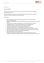
User manual ACOWA INSTRUMENTS SPIDER is a universal control with functions for pump control, data collection, alarm management, groundwater lowering etc. SPIDER is developed and produced in Denmark. SPIDER complies with all specifications regarding placement of electronic components in harsh environments. • Advanced 1 and 2 pump control with empty/fill function and internal pump alternation. • Build-in GSM/GPRS Modem. • Multiprotocol, Modbus RTU/TCP & COMLI. SPIDER auto-detects the protocol used by the SCADA system. • Click connection for a joystick-equipped graphic 2,4" OLED display directly...
Open the catalog to page 5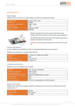
User manual ACOWA INSTRUMENTS installationPower supply SPIDER must be connected to a supply voltage according to the specifications below. ACOWA INSTRUMENTS, Industrivej 10, 8305 Sams0 - VAT-no: 36562919 - mail: [email protected] - Phone: +45 7221 7979
Open the catalog to page 6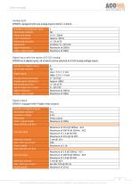
ACOWA INSTRUMENTS Analog input SPIDER is designed with one analog input 0-20mA / 4-20mA. ACOWA INSTRUMENTS, Industrivej 10, 8305 Sams0 - VAT-no: 36562919 - mail: [email protected] - Phone: +45 7221 7979
Open the catalog to page 7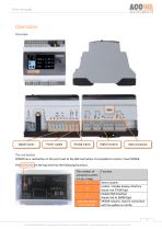
User manual Operation Overview Digital Inputs Power supply Analog inputs Digital outputs The red button SPIDER has a red button on the print next to the SIM card where it is possible to restart / reset SPIDER. The red button on the top print has the following functions: The number of activations within a 5 sec. range. 1 3 5 Hold the button in for 10 sec. Reset modem Enable / disable display interface (baud rate 57600 bps) Enable HMI interface (baud rate to 38400 bps) SPIDER restarts. Used in connection with fw-update or similar. 7 ACOWA INSTRUMENTS, Industrivej 10, 8305 Samsø - VAT-no: 36562919...
Open the catalog to page 8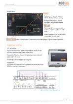
User manual SPIDER diodes Status Flashes every 5 seconds: status to indicate that the device is working. Double flash means that the HMI interface / Oled display is enabled. Net-status Flashing fast (2 times per second) modem is not connected to the GSM mast. Flashes slowly (once per second) and is connected to the GSM mast. Modem-status flashes when a modem is connected to the GSM mast and a signal strength is detected. Externel unites I/O module For connections of more signals, it is possible to connect an I/O module with multiple digital- and analog inputs. The module allows for a total of...
Open the catalog to page 9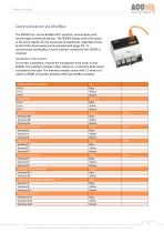
User manual ACOWA INSTRUMENTS Communication via ModBus The SPIDER can, via the ModBus-RTU protocol, communicate with several types of external devices. The SPIDER always writes the values in the same register for the same type of equipment, regardless of the brand of the device being communicated with (page 35). To communicate via ModBus, a serial interface module for the SPIDER is required. For correct installation, remove the transparent front cover on the SPIDER. The interface module is then clicked on, so that the RJ45 socket is located to the right. The interface module comes with 1.5 meters...
Open the catalog to page 10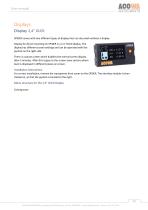
User manual Displays Display 2,4” OLED SPIDER comes with two different types of displays but can also work without a display. Display for direct mounting on SPIDER is a 2.4 "OLED display. The display has different screen settings and can be operated with the joystick on the right side. There is a pause screen which disables the normal screen display after 5 minutes. After this it goes to the screen saver picture where level is displayed in different places on screen. Installation instructions. For correct installation, remove the transparent front cover on the SPIDER. The interface module is...
Open the catalog to page 11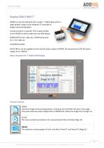
User manual Display EAGLE HMI 7” SPIDER can also be delivered with a larger 7” HMI display where a larger graphic image can be designed. It is possible to design customized graphics. A serial overprint is required. This is easily clicked on the SPIDER as well as cable sets and HMI display. SPIDER HMI kit incl. cable sets, SPIDER serial print incl. 1.5m cable set Installation guide EAGLE HMI is not be supplied via the internal power supply of SPIDER. We recommend a 24V DC power supply of min. 500mA. Menu structure for 7” EAGLE HMI Display Submenu functions Function buttons HOME Overview image...
Open the catalog to page 12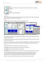
User manual INFO The submenu contains data for all counters, meters and status bits on in- and outputs (page 16) ALARM Alarm list of all alarms (Page 16) LED lights When installed correctly, the upper “PWR” lamp will have a solid yellow light. The middle "CPU" will flash green and the bottom "COM" will flash rapidly red. HOME. The home screen is the overview picture for the entire pumping station. In the upper part of the picture, is the pump station data placed. In this case, the station is called SPIDER followed by date and time. On the left side of the picture, the pump station is shown. At...
Open the catalog to page 13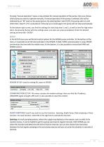
User manual ACOWA INSTRUMENTS Pressing "manual operation" opens a new window for manual operation of the pumps. Here you choose which pump you want to operate manually. If manual operation of the pumps is selected, this will be indicated by an "M" mark on the pump picture. By selecting Man. Start P1/P2, the pumps will run until either Man. Stop P1 / P2 is activated or if the pop-up is closed again, the pump will not stop automatically. At the bottom right corner, you find the settings for start/stop level 1 and 2, as well as level for high water alarm. By pressing the bar with the settings value,...
Open the catalog to page 14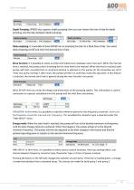
ACOWA INSTRUMENTS Depth Pumping: SPIDER also supports depth pumping. Here you can choose the time of day for depth pumping, and the days between depth pumping. Depth pumping Daily emptying: It is possible to have SPIDER run an emptying function at a fixed time of day. You select Daily emptying on/off and enter the desired time of day. Daily emptying | Each day Rinse function: It is possible to select an interval of whole hours between each rinse start. When the interval time is reached, the pump control is waiting for the rinse level to be reached. When the level is reached, both pumps will start,...
Open the catalog to page 15All ACOWA INSTRUMENTS catalogs and technical brochures
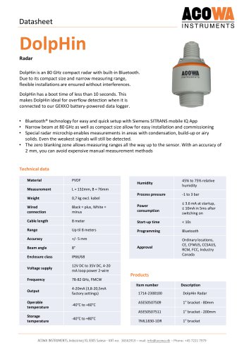 DolpHin
1 Page
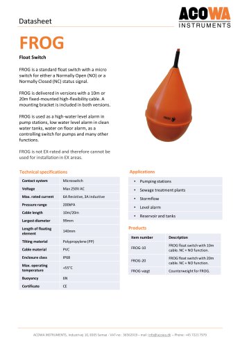 FROG
FROG1 Page
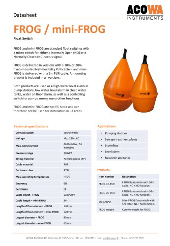 FROG / mini-FROG
1 Page
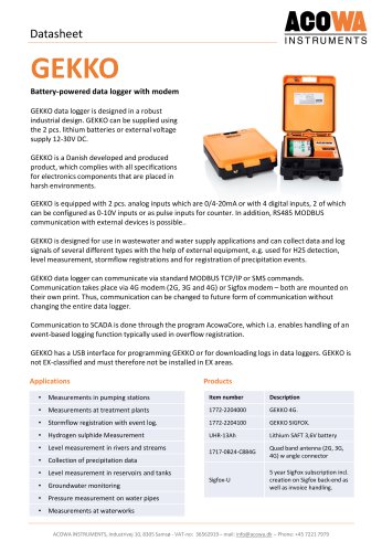 GEKKO Datasheet
3 Pages
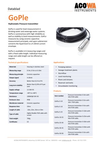 GoPle
GoPle1 Page
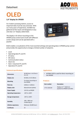 OLED
OLED1 Page
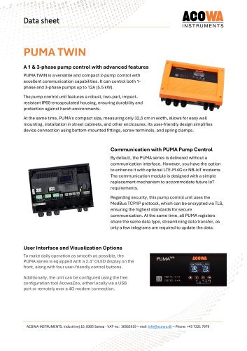 PUMA TWIN
5 Pages
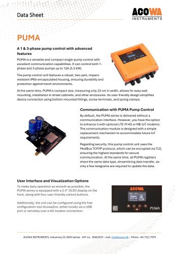 PUMA
PUMA5 Pages
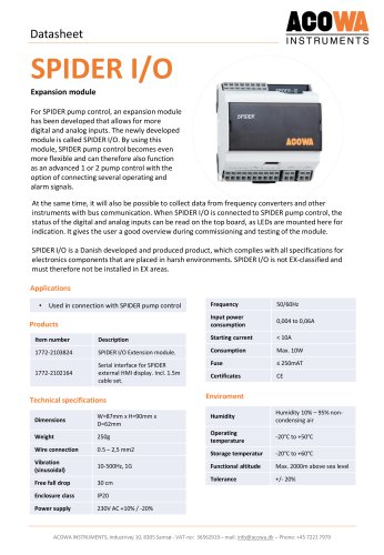 SPIDER I/O
2 Pages
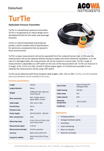 TurTle
2 Pages
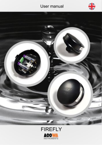 FireFly
13 Pages
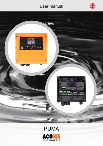 PUMA
PUMA39 Pages
 GEKKO
GEKKO29 Pages
 ACOWA hiVe
28 Pages
 Mini-GoPle
2 Pages
 SPIDER
2 Pages
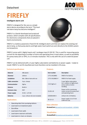 FIREFLY
1 Page
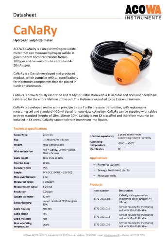 CaNaRy
1 Page
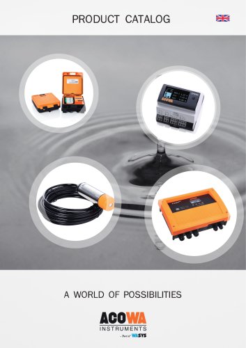 PRODUCT CATALOG
13 Pages
- Automation software solution
- Management software solution
- Data logger
- Pressure transmitter
- Process software
- Real-time software
- Windows software
- Analog pressure transmitter
- Liquid level detector
- Control software
- Temperature datalogger
- Monitoring software solution
- Waterproof pressure transmitter
- Membrane pressure transmitter
- Stainless steel pressure transmitter
- LED display panel
- Relative pressure transmitter
- Float level switch