- Catalogs
- ABUS Kransysteme GmbH
- Electric chain hoists
- Company
- Products
- Catalogs
- News & Trends
- Exhibitions
Electric chain hoists
1 /13Pages

Electric chain hoists
1 /13Pages
Catalog excerpts
ELECTRIC CHAIN HOISTS Product information
Open the catalog to page 1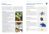
ABUS Electric chain hoists | Description of the standard equipment DESCRIPTION OF THE STANDARD EQUIPMENT TECHNICAL DETAILS & USEFUL INFORMATION ON THE ABUCOMPACT GM2 TO GM8 The new generation of ABUCompact chain hoists feature a electric chain hoist range and introduction dates are given in fresh new design and convincing technical solutions. The 3 the selection table. Why not take advantage of the additional phase 400 volt hoists units are available in four different sizes features described from page 6 onwards. The small GMC hoist to reliably handle loads from 80 kg through 4000 kg. The motor...
Open the catalog to page 2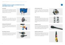
TECHNICAL DETAILS & USEFUL INFORMATION ON THE ABUCOMPACT GM2 TO GM8 Chain system The chain system consists of a high-precision chain sprocket The electronic control features no-wear semiconductor entirely surrounded by the chain guide. Both the chain sprocket technology. This configuration allows considerable weight and the chain guide are of modular design, allowing easy and space savings compared with mechanical contactors. replacement without the need to spend time and money (Standard equipment for GM8, optional for GM2, GM4 and dismantling the hoist to reach the parts. Slipping clutch Profile...
Open the catalog to page 3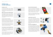
ABUS Electric chain hoists | Optional extras OPTIONAL EXTRAS FOR MORE CONVENIENCE Operating hours meter Electronic limit switch (two positions) An operating hours meter allows a realistic assessment The electronic limit switch features two programmable shut- of the work actually performed by a hoist. The operating down points for even safer operation. The shut-down points hours indicated can be used for calculating the remaining for highest and lowest hook position can be programmed service life of the hoist in accordance with FEM 9.755. With individually using a teach-in button on the pendant...
Open the catalog to page 4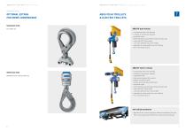
ABUS Electric chain hoists | Optional extras ABUS Electric chain hoists |ABUS push trolleys & electric trolleys OPTIONAL EXTRAS FOR MORE CONVENIENCE ABUS PUSH TROLLEYS & ELECTRIC TROLLEYS Suspension hook For mobile use Safety load hook Reliable secured closing under load ABUS HF push trolleys • sturdy design with roller bearings • virtually no maintenance required • machined rollers • fitted with drop stop and wheel climb prevention lugs • colour RAL 5017 (traffic blue), suits many different chain hoist models • adjustable for flange widths from 42 to 400 mm ABUS EF electric trolleys • sturdy...
Open the catalog to page 5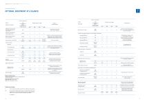
ABUS Electric chain hoists | Optional extras OPTIONAL EQUIPMENT AT A GLANCE Options (Equipment package) Electric movements H/S Possible scope of supply Lifting/lowering H/S/KF Notes on scopae of supply Electric movements H/S Possible scope of supply Lifting/lowering Requirements Additional connector plug 5-pole power supply and direct control required Operating hours meter Only for an operating voltage of extension necessary Connector plug BJS24 for control cable on site Electric trolley travelling control extension Pendant control with additional buttons, H/S/KF X X X X trolley motor cable,...
Open the catalog to page 6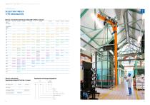
ABUS Electric chain hoists | Selection tables Type designation SELECTION TABLES TYPE DESIGNATION Electric chain hoists (operating voltage 400 V, 50 Hz, 3-phase) Main lifting speed 3 m/min 4 m/min 5 m/min 12 m/min 16 m/min 20 m/min Electric chain hoists(operating voltage 230 V, 50 Hz, 1 phase) Explanation of the type designation Hoist Trolley Main lifting speed 6 m/min 12 m/min
Open the catalog to page 7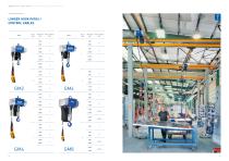
ABUS Electric chain hoists | Longer hook paths / control cables LONGER HOOK PATHS/ CONTROL CABLES No. of Hook path Chain container falls mm size No. of Hook path Chain container falls mm size
Open the catalog to page 8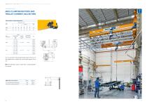
ABUS Electric chain hoists | ABUS clamping buffers and trolley current collectors ABUS CLAMPING BUFFERS AND TROLLEY CURRENT COLLECTORS Selection table for shaped clamping buffers Size Gummi Flange width Flange ABUS electric Ref. range thickness chain hoists Can be used with S 235 parallel flanged beams (free fom oil and grease) and for trolleys with a max. travel speed of 36 m/ min. Note: For buffering a trolley on both sides, 2 clamping buffers are required. ABUS trolley current collectors Weight Order N° For the festoon power supply system 3,7 kg 309728 For the power conductor type KBH 2,4...
Open the catalog to page 9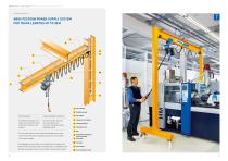
ABUS Electric chain hoists | ABUS festoon power supply system *The riser cable from the mains switch and cabling from the mains switch to the terminal box, including accessories, are not included in the scope of supply. The voltage drop must be taken into consideration for the design of the festoon system. The festoon system is prefabricated, i.e. supplied with the flat cable on the cable carriers, current collector carrier and end clamp. Fixed components Transitional terminal box, end clamp, current collector carrier, mains switch, trolley current collector Length-dependent components Flat cable...
Open the catalog to page 10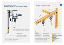
ABUS Electric chain hoists | ABUS power supply system with mobile control ABUS Electric chain hoists | ABUS safety conductor system ABUS POWER SUPPLY SYSTEM WITH MOBILE CONTROL FOR TRACK LENGTHS UP TO 30 M ABUS SAFETY CONDUCTOR SYSTEM In the standard version, the pendant control is attached directly to the hoist by a quick plug-type connector. With this alternative, the pendant control can be moved along the trolley track independently from the hoist. The additional components required include rail, flat cable, cable carrier and control carrier with connector. The basic design is the same as...
Open the catalog to page 11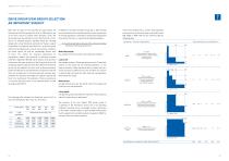
ABUS Electric chain hoists | Drive group (FEM group] selection DRIVE GROUP (FEM GROUP) SELECTION AN IMPORTANT SUBJECT Apart from the type of hoist required, the load capacity, the hook path and the lifting speed, the drive or FEM group is one of the main criteria to consider when selecting a hoist. The drive group must be selected to ensure that the hoist is fit for use for its intended purpose. Standard hoists are normally designed for a mean theoretical service life of 10 years, subject to operation in accordance with FEM 9.511. If the drive group selected is not appropriate in view of actual...
Open the catalog to page 12All ABUS Kransysteme GmbH catalogs and technical brochures
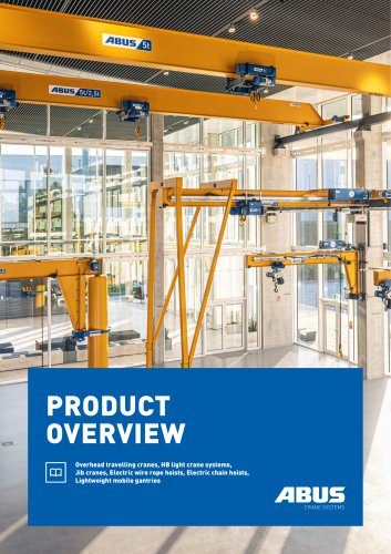 The Product Overview
23 Pages
 ABUS Component-Catalog B
13 Pages
 ABUS 2025
23 Pages
 ABUS Component Catalog A
13 Pages
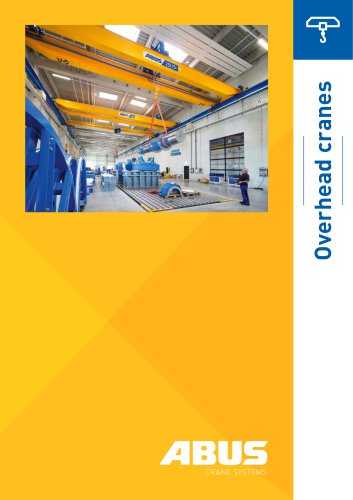 Overhead cranes
23 Pages
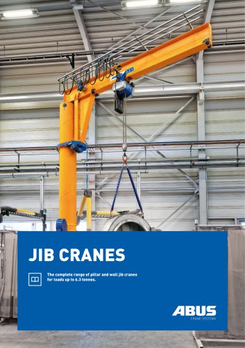 Jib Cranes
13 Pages
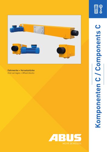 Component Catalogue C
9 Pages
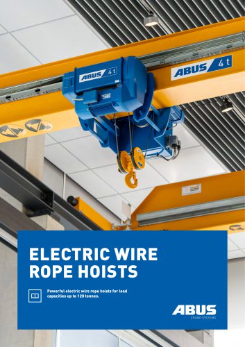 Electric wire rope hoists
13 Pages
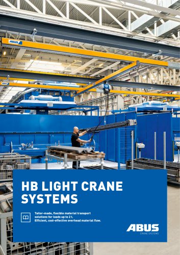 HB light crane track systems
17 Pages
 ABUS LPK mobile gantry
2 Pages
- Abus jib crane
- Mobile gantry crane
- Abus overhead travelling crane
- Lifting jib crane
- Pillar jib crane
- Abus single-girder overhead travelling crane
- Abus cable hoist
- Abus electric cable hoist
- Double-girder bridge crane
- Wall-mounted jib crane
- Rotary jib crane
- Abus hanging overhead travelling crane
- 270° jib crane
- 360° jib crane
- 180° jib crane
- Lightweight gantry crane
- Monorail overhead traveling crane