
- Catalogs
- ABICOR BINZEL
- AB Series


- Products
- Catalogs
- News & Trends
- Exhibitions
AB Series

AB Series
The AB Series manual welding torches are designed for welding carbon and alloy steel materials. They require a welding power supply and comply with directive EN 60 974-7. The torches include a torch neck, handle, and cable assembly with connectors.
Technical Data
Operating temperatures range from -10°C to +40°C, with storage temperatures from -25°C to +55°C. The torches use DC voltage, typically with a positive electrode polarity, and are compatible with CO2 and mixed gas M21 shielding gases. They support commercially available round wires and have a voltage rating of 113 V peak value.
Safety Instructions
Four levels of warning signs are used: Danger, Warning, Caution, and Note. In emergencies, power and gas supplies should be immediately interrupted.
Putting into Operation
Instructions are provided for equipping the torch neck, changing or adjusting the torch neck, mounting the wire guide liner, connecting the torch to the machine, setting the shielding gas quantity, and feeding in wire. Safety precautions include switching off power and gas supplies during maintenance.
Operating Elements
Welding is initiated by pressing the trigger on the handle and stopped by releasing it.
Removal from Service
After use, wait for the shielding gas flow to subside, switch off the power supply, and close the gas cylinder valve.
Maintenance and Cleaning
Regular maintenance involves unscrewing the torch, replacing worn parts, cleaning the wire guide liner with compressed air, and ensuring clean contact surfaces. Protective clothing, especially safety goggles, is recommended during cleaning.
Notes
Contact information for ABICOR BINZEL and its subsidiaries is provided for further assistance.
Catalog excerpts

TECHNOLOGY FOR THE WELDER´S WORLD. Operating instructions AB Series MIG/MAG Welding Torches
Open the catalog to page 1
EN English Translation of the original operating instructions © The manufacturer reserves the right, at any time and without prior notice, to make such changes and amendments to these operation Instructions which may become necessary due to misprints, inaccuracies or improvements to the product. Such changes will however be incorporated into subsequent editions of the Instructions. All trademarks mentioned in the operating instructions are the property of their respective owners. All brand names and trademarks that appear in this manual are the property of their respective owners/manufacturers. Our...
Open the catalog to page 2
AB Series Torches 1 Designated Use 1 Designated Use The AB series manual welding torches are used for safety welding of carbon steel and alloy steel materials. They consist of the torch neck with equipment parts and wearing parts, handle and cable assembly with Panasonic connector (or OTC/Euro connector). They correspond to the directive EN 60 974-7 and are not considered to be devices having their own functions. Arc welding can only be carried out in connection with a welding power supply. 1.1 Marking This product fulfills the requirements that apply to the market to which it has been introduced....
Open the catalog to page 3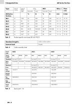
1 Designated Use AB Series Torches Tab. 5 Spare parts' list
Open the catalog to page 4
AB Series Torches 2 Safety Instructions Tab. 6 Contact tip list IStandard contact tip for AB20 2 Standard contact tip for AB35/50 2 Safety Instructions Observe the enclosed document Safety Instructions. 2.1 Classification The warning signs used in the operating instructions are divided into four different levels and are shown prior to specific work steps. Arranged in descending order of importance, they have the following meaning: Describes imminent threatening danger. If not avoided, it will result in fatal or extremely critical injuries. A WARNING Describes a potentially dangerous situation....
Open the catalog to page 5
3 Putting into operation 3 Putting into operation DANGER Risk of injury due to unexpected start-up. For the entire duration of maintenance, servicing, dismounting and repair work, the following instructions must be adhered to: • Switch off the power supply. • Close off the gas supply. • Disconnect all electrical connections. 3.1 Equipping the torch CAUTION Risk of injury Piercing or puncture caused by electrode tip. • Do not reach into the danger zone and wear protective gloves. 3.1.1 Equipping spare parts onto the torch neck Equip the torch neck according to the following figure: Gas diffuser...
Open the catalog to page 6
3 Putting into operation 3.2 Mounting the wire guide liner 1 Lay the torch straight out and unscrew the gas nozzle as well as the contact tip from the torch neck. 2 Slide the wire guide liner into the torch up to the Panasonic connector; for the torches with Euro or OTC connector, unscrew the position holder nut on the connector, insert the wire guide liner in and then screw the position holder nut back on again. 3 Fold the torch side cable to a degree of 180°, cut off the wire guide liner at the end of the tip holder. 4 Pull out the wire guide liner. 5 Sharpen the wire guide liner to an angle...
Open the catalog to page 7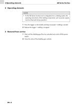
4 Operating elements NOTE • As the AB Series Torches torch is integrated into a welding system, the operating instructions of the welding components, such as power supply, must be observed during operation. 1 Press the trigger on the handle and keep it pressed = welding is started. 2 Release the trigger = welding is stopped. 5 Removal from service 1 Wait until the shielding gas flow has subsided and switch off the power supply. 2 Close the valve of the shielding gas cylinder.
Open the catalog to page 8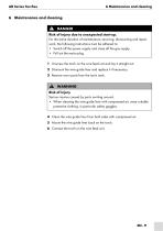
AB Series Torches 6 Maintenance and cleaning AB Series Torches 6 Maintenance and cleaning A DANGER Risk of injury due to unexpected start-up. For the entire duration of maintenance, servicing, dismounting and repair work, the following instructions must be adhered to: • Switch off the power supply and close off the gas supply. • Pull out the mains plug. 1 Unscrew the torch on the wire feed unit and lay it straight out. 2 Dismount the wire guide liner and replace it if necessary. 3 Remove worn parts from the torch neck. A WARNING Risk of injury Serious injuries caused by parts swirling around. •...
Open the catalog to page 9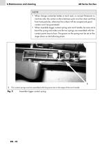
NOTE • When change contact-tip holder or torch neck, or connect Panasonic to machine side, the contact surface between parts must be clean and free from hard particles, otherwise the surface will be scraped and good contact won’t be guaranteed. • When assemble trigger contact spring onto torch handle, be care not to bend the spring and make sure the two springs are assembled with the contact points face to face. The groove on the spring must be set on the stage shown as the following photo. The contact springs must be assembled with the groove set on the stage of the torch handle Assemble trigger...
Open the catalog to page 10
Guangzhou ABITEC Welding Equipment Company Ltd. An Enterprise of ABICOR BINZEL Group Add: NO. 42 Dongpeng Road , East District, GETDD, Guangzhou, P.R. China Pos: 510530 Tel: +86-20-82265568 Fax: +86-20-82265598 Email: [email protected]
Open the catalog to page 12All ABICOR BINZEL catalogs and technical brochures
 TIG CATALOG 4.2
48 Pages
 Operating instructions
40 Pages
 ABIBLUE
2 Pages
 Plasma
24 Pages
 MIG_MAG
60 Pages
 Image brochure
24 Pages
 EWR
EWR8 Pages
 WH Tandem W800
8 Pages
 W600 Torch Series
6 Pages
 ABIMIG® A T VARIO
9 Pages
 ABIMIG® A T
12 Pages
 ABIMIG® A T COMBI
16 Pages
 ABITIG® GRIP 500 W
4 Pages
 E3® Brochure
4 Pages
 ABIPLAS® WELD
6 Pages
 Pure Power ...
6 Pages
 iCAT
iCAT6 Pages
 MFS V2
8 Pages
 RAB Plus
2 Pages
 ROBO product catalogue 3.0
116 Pages
 MB GRIP SC
2 Pages
 TIG-Torch overview 1.0/V1
514 Pages
 TIG-Spare Parts List
120 Pages
 MIG/MAG-Spare Parts 2.0/V1
176 Pages
 Accessories- Catalogue 2.0/V2
28 Pages
 MIG/MAG- Catalogue 3.0/V1
44 Pages
 TIG product catalogue 3.1 / V1
40 Pages
 gouging torch G3000 / G4000
4 Pages


- Metal stand
- Arc welding torch
- Steel bracket
- Stainless steel bracket
- Air-cooled welding torch
- MIG-MAG welding torch
- Water-cooled welding torch
- TIG welding torch
- Cutting torch
- Cable support
- Manual welding torch
- Manual cutting torch
- Plasma cutting torch
- Welding torch with fume extraction
- Component support
- Flange holder
- Robotized welding torch
- Spring support
- Workpiece support
- MIG welding torch