Aberlink CAD Comparison
1 /2Pages

Aberlink CAD Comparison
1 /2Pages
Catalog excerpts
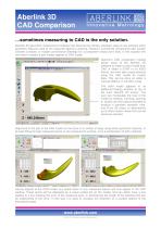
Aberlink 3D CAD Comparison …sometimes measuring to CAD is the only solution. Aberlink 3D geometric measurement software has become the industry standard, easy-to-use software when geometric features need to be measured against a drawing. However, sometimes components also contain complex surfaces, or maybe conventional drawings for a component simply don’t exist. In this situation the only way to inspect a part maybe against its CAD model. Aberlink’s CAD comparison module allows users of the Aberlink 3D software to import a solid model from CAD in either a STEP or an IGES format, and then take measurements using the CAD model as master data. This can be done on either a manual CMM or in full CNC mode. The solid model appears in an additional floating window on top of the main Aberlink 3D screen. The user can manipulate the view of the model by rotating, zooming, panning or simply use the buttons provided to produce a standard isometric view, one of six 2D views, or alternatively up to three custom views that can be saved as required. Alignment of the part to the CAD model can be done in a number of ways using either geometric features, or by best-fitting through measured points on the component’s surface, or by a combination of both methods. Having aligned to the CAD model, any points taken in any measured feature will now appear in the CAD window. These points will be displayed as a colour-coded dot on the model, and can either have a line leading to a box showing the error of the measured point, or alternatively the length of the attached line can be proportional to the error. In this way it is easy to visualise the distortion of a surface relative to the theoretical model. www.aberlink.com ©1993-2011Aberlink Innovative Metrology LLP
Open the catalog to page 1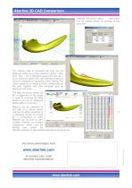
Aberlink 3D CAD Comparison Detailed information about each point can be viewed simply by clicking on the error box: The colours used to represent the error can be displayed either as a colour spectrum (green = zero error, blue = out of tolerance below limit and red = out of tolerance above limit, with different shades of colours in between) or as distinct colour bands. The colour spectrum or bands are fully configurable by the user, together with other variables such as tolerance and scale. The best-fit function allows full 3D re-alignment of the model in order to minimise the RMS errors of any...
Open the catalog to page 2All Aberlink catalogs and technical brochures
 CMM Fixture Kit
2 Pages
 CMM Camera System
2 Pages
 product catalogue 2015
20 Pages
 Touch screen joystick
2 Pages
 Aberlink Vision (Data Sheet)
2 Pages
 Aberlink 3D Vision
2 Pages
 Aberlink 3D
2 Pages
Archived catalogs
 Project X
4 Pages
 Zenith too
8 Pages
 Axiom too
8 Pages
- Visible imager
- Computer-aided design software
- Programming software
- CCD video camera
- Spark optical emission camera module
- Coordinate measuring machine
- Multi-sensor coordinate measuring machine
- Bridge coordinate measuring machine
- Vision system
- Large part coordinate measuring machine
- Machine vision system
- Automated coordinate measuring machine
- Vision system software
- Manually-controlled coordinate measuring machine
- Workshop coordinate measuring machine