- Catalogs
- Abbey Electronic Controls
- ZAX27A ISOLATED MAINS CONTROL MODULE
ZAX27A ISOLATED MAINS CONTROL MODULE
1 /20Pages

ZAX27A ISOLATED MAINS CONTROL MODULE
1 /20Pages
Catalog excerpts
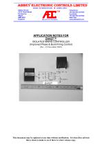
Abbey House 19-21 Fleet Street Pemberton Wigan WN5 0DU England APPLICATION NOTES FOR ZAX27™ ISOLATED MAINS CONTROLLER (Improved Phase & Burst-Firing Control) (Rev. 2.0 November 2003) This document may be updated at any time without notification. It is therefore advised that a check is made to see if there is a later release copy.
Open the catalog to page 1
The ZAX27™ is a fully isolated and elegant device for the accurate control of alternating current voltage of any amplitude up to 300V rms. It achieves this through a d.c. control voltage. It exists in two versions, A and B. The ZAX27A has a built-in triac allowing it to drive loads of up to 3A peak r.m.s. and is therefore a fully self-contained unit. It can be used to drive external triacs or back-to-back thyristors giving it, in effect, unlimited power capability. The ZAX27B, on the other hand, is optimised for driving thyristor modules and therefore has no inbuilt triac. It is most useful when...
Open the catalog to page 4
Phase versus Burst Control Both phase control and burst control are well-established methods for controlling alternating current voltages. Phase control is more versatile and suitable to a wider range of situations than is burst control. It however has the major disadvantage of being intrinsically very noisy. Where the electrical noise generated cannot be eliminated (due to power level, for example) its use may be precluded 1 . Burst control on the other hand does not suffer from noise in the same way as phase control. It can work with full half sine wave cycles. This makes it possible to ensure...
Open the catalog to page 5
Overheat Shut Down There is also the inclusion of an in-module overheat shut down facility. If the module’s internal temperature should rise too high it will automatically shut down until it has cooled down to an acceptable limit before turning on again automatically. For this feature to be effective the thermal overload must not be too severe, otherwise the temperature will rise faster than the thermal sensor could react leading to internal failure. 2.4 Soft Start Facility The ZAX27™ has a soft-start feature which will gently ramp up the power output from 0% to 100% over a period, typically...
Open the catalog to page 6
A low logic on the mode pin 3 puts the ZAX27™ into its burst mode whilst a high logic will put it into the phase mode. This pin should not be left floating as it may otherwise be in an indeterminate state. 3.1.3 The inhibit pin suppresses any output from the ZAX27A™ when a logic high is applied to its input. The pin is also used to modify the input range of the module. It has an internal 10kΩ pull down resistor and can therefore be left unconnected if not used. Since this pin has an internal 10k pull down resistor, all that is required in order to change the input range is another 10k resistor...
Open the catalog to page 7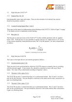
High Side pins ZAX27A™ Interchangeable mains input and output. These are the terminals of an internal triac and are therefore not polarity sensitive. 3.2.2 Current Overload Input (Pins 11 &12) These pins are the inputs for implementing current limiting on the ZAX27A. Refer to Figure 7 on page 17 for details on how to implement current limiting. 3.2.3 The bias pin is a later provision on the ZAX27A™ to allow reliable operation with AC supplies below 150V. With the bias it is now possible to operate with any AC supply down to 12V or less. A bias resistor should be connected between pins 9 & 13...
Open the catalog to page 8
Technical Specifications (absolute maximum ratings) 4.1 Low Voltage Side Supply Voltage, Vs Max Supply Current Control Input Range High Logic (pins 4 & 5) Low Logic (pins 4 & 5) Supply Voltage Rejection Temperature Coefficient Maximum Input (all pins) 4.2 Error Amplifier: Input Offset Voltage ±5 mV Input Offset Current ±50 nA Common Mode Input Range 0 - 5 V kV V 50 Hz A rms A rms A (< 10 ms) W W mA A (< 10 ms) 4.3 High Voltage Side Isolation Voltage8 5 Maximum Peak Load Current 3.0 Maximum Peak Drive current 1.0 Operating Temperature Overheat Shutdown Overheat Reset...
Open the catalog to page 9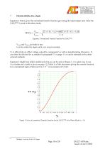
PHASE MODE (Pin 3 high) Equation 2 below gives the normalised transfer function governing the input/output ratio when the ZAX27™ is used in the phase mode. Equation 2 Normalised Transfer Function for ZAX27™. Vload and Vmains are both in rms vi is the control dc input and vo is a circuit constant. Vo is effectively an offset voltage caused by components' as well as manufacturing tolerances. It can either be allowed for as detailed in paragraph 5.1 on page 11 or can be trimmed out by other external methods. Equation 2 might look rather cumbersome but, as can be seen in Figure 1, it is quite easy...
Open the catalog to page 10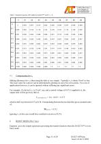
Table 1 Transfer Function (TF) table for ZAX27™ with Vo = 0. 5.1 Compensating for vo Making allowance for vo when using the table is very simple. Typically vo is about 10 mV or less. The exact value for a device can be determined by plotting its curve for a few points. For a lot of applications however, it can be ignored without suffering any significant errors. For example, if a device's v0 is 25 mV, say, and a control voltage of 0.4 V is applied to it, the output ratio will be given by that of, Vcontrol(effective) = 0.4 - 0.025 - 0.375 which is half way between 0.37 an 0.38. Extrapolating between...
Open the catalog to page 11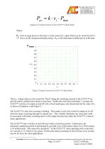
Pav = k ⋅ vi ⋅ Pmax Equation 3 Transfer Function for the ZAX27™ in Burst Mode. Where Pav is the average power to the load, vi is the control d.c. input which can be varied from 0 to 1V. k is a circuit constant (nominally unity), Pmax is the maximum available power to the load. Figure 2 Transfer Function for ZAX27™ in Burst Mode. The d.c. voltage achieves this control by "burst" firing the switching element of the ZAX27™ on and off within a defined time frame or time base. Within this time base (nominally 1 second), the ZAX27™ switches its output on and off with a fixed mark/space ratio determined...
Open the catalog to page 12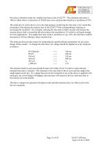
Provision is therefore made for variable time base on the ZAX27™. The minimum time base is 100 ms which allows a maximum of 10 half sine waves and provides therefore a resolution of 10%. The mode pin (3) on the device serves the dual purpose of allowing the time base to be varied thus increasing or decreasing the reaction time of the ZAX27™ but correspondingly reducing or increasing the resolution. For example, reducing the time base to half a second will increase the reaction time to half a second but this also reduces the resolution to 2% which is still good enough for most applications. If...
Open the catalog to page 13All Abbey Electronic Controls catalogs and technical brochures
 AEC
AEC1 Page
 WSX53
WSX534 Pages
 WSX53G06 PRECIPITATION
4 Pages
 WSX53B WEATHER SENSOR
4 Pages
 FX37FSA
1 Page
 WSX53A48 PRECIPITATION
4 Pages
 FX37-P16
1 Page
 WSX53A24 PRECIPITATION
4 Pages
 WSX53A12 PRECIPITATION
4 Pages
 WSX53A06 PRECIPITATION
4 Pages
 MPC34A DUAL MODE
2 Pages
 M021P MODULATING PUMP CONTROLLER
16 Pages
 WSX53
WSX534 Pages


- Bourn And Koch pressure switch
- Bourn And Koch circuit breaker
- Bourn And Koch electronic filter
- Bourn And Koch waterproof pressure switch
- Gas pressure switch
- Bourn And Koch flow switch
- Differential pressure switch
- Current circuit breaker
- Air pressure switch
- Pump controller
- AC circuit breaker
- Manual reset circuit breaker
- Thermal circuit breaker
- Current amplifier
- IP66 pressure switch
- Active electronic filter
- Industrial flow switch
- High-pass electronic filter
- EMC filter
- Thermal flow switch