- Catalogs
- Abbey Electronic Controls
- FX30LWD DUAL FAN SPEED IGNITION CONTROLLER
FX30LWD DUAL FAN SPEED IGNITION CONTROLLER
1 /17Pages

FX30LWD DUAL FAN SPEED IGNITION CONTROLLER
1 /17Pages
Catalog excerpts
Abbey House 19-21 Fleet Street Pemberton Wigan WNS ODU England ISS.1.02/96 APPLICATION NOTES FOR FULL SEQUENCE CONTROL BOARD (OEM Copy) This document may be updated at any time without notificatioa It is therefore advised that a check is made to see if there is a later release copy.
Open the catalog to page 1
1 Introduction 1.1 The FX30XXX1 is an electronic full sequence control (FSC) board designed for combustion appliances. 1.2 It is a dual fan speed controller allowing two air rates for the appliance under control. It incorporates, by design, features to allow many variations of the board as will be explained later under "Nomenclature". 1.3 It provides electronic ignition and flame detection by means of an ionisation probe which can also be configured as the spark electrode. Otherwise the spark and flame electrodes are kept separate. The control is also available with a volatile or a nonvolatile...
Open the catalog to page 3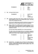
2.3 IB2:- Air Pressure Switch terminal. 2.4 IB4:- Terminal for safely lockout device which is supplied with each board for panel mounting in the case of a non-volatile lockout board. This device carries with it an integral reset button. In the case of a volatile lockout control, this terminal is not present as it is replaced with an on-board volatile lockout device (a PTC thermistor). 2.5 IBS:- When a change-over to a different preset fan speed is required, 24 V d.c. is applied to pins 1 & 2 of this pin header for 2-speed RSF application. The fan is thus switched between high and low speed...
Open the catalog to page 4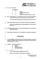
2.8 IBS:- Lockout indicator4. A neon indicator connected to this terminal will light up if a lockout has occurred, or if the lockout device is missing or faulty. The neon may flicker during ignition but will extinguish after flame detection. 2.9 TAG1:- Flame detection electrode. Not required for a single probe arrangement If flame is not established within a specified safety time, the board proceeds into lockout 2.10 TAG2:- ignition electrode, hot end. In the case of a single probe control, this terminal also detects the flame. 2.11 TAG3:- Ignition electrode, earth end. Not required for a...
Open the catalog to page 5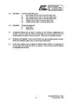
3.1.2 2nd Letter:- Lockout mode/Safety time. L - Non-volatile lockout with 5 seconds safety time. M - Non-volatile lockout with 10 seconds safety time. N - Non-volatile lockout with 15 seconds safety time. V - Volatile lockout with 10 seconds safety time. W - Volatile lockout with 15 seconds safety time. 3.1.3 3rd Letter:- Probe(s) arrangement D - Dual probe. 3.2 It therefore follows that at least 32 versions of the FX30xxx configurations are possible. Not all of these are viable commercially and it will be expected that the actual number of variants will be much less. There are...
Open the catalog to page 6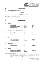
4 Classification. 4.1 The classification of this control is:- FMRLXK or FMRVXK depending on variant Please refer to nomenclature on page 5. Supply Voltage Tolerance +10, -15 % 5.2 Power Consumption:- (Excluding all peripherals) Maximum Peak 75 VA 5.5 ignition:-Maximum Spark Frequency 50 Sparks/Sec. Minimum Spark Frequency No limit Where there have been design revisions, please note that the specification refers to that of the existing current issue of the design which may be different from the original specification.
Open the catalog to page 7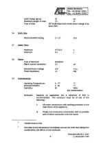
Spark Energy (gross) 20 mj Maximum Length of Lead 1.5 m Type of Lead EHT Multi-strand with break down voltage of at 5.6 Spark Gap:-Recommended Setting 3 +1,-0 mm Maximum Minimum 5.8 Flame:-Type of detection Ionisation. Flame Current Sensitivity:- 2.0 pA Nominal Probe Voltage 230 V a.c (No condensation) Enclosure:- Depends on application but a minimum of IP40 is recommended. The enclosure must be of one of the following:-I) All-metal construction with earthing provision to the main frame of the appliance, ii) Totally non-conductive construction with no possible path...
Open the catalog to page 8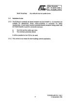
Board Mounting:- Any attitude but not upside down. 5.10 Exclusions To Use. 5.10.1 The FX30xxx is currently not phase sensitive but the FX30SFT is. It is therefore not suitable for applications where phase-sensitivity is necessary for safety requirements. In such cases, however, provided double insulation wiring (cable with an overall sheath) is used for connection between a) The FX30 and the safety gas valve b) The overheat protection device it will be possible for the FX30 to be used. 5.10.2 This control is not meant for inter-building controls application.
Open the catalog to page 9
Appendix L 6.1 Peripheral Wiring Diagram. 6.2 Timing Diagram. (Ignore the fan for the FX30SPT). 6.5 Data on FX30PPT Fan Proving Board.
Open the catalog to page 10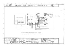
© Ml,. ABBEY ELECTRONIC CONTROLS un |N0TES<#> : -*** Uol ue depends on Appl i c At i on . Ootted lino shoos alternative connection for Default High Fan use. ALL RESISTORS 0.25U 5/. PLL ZENERS 05U ALL PIMENTIONS IN mm Pin 'S TP 1DP z +0 .1 mm , PIM'S TO 2DP z +0.02 mir^ ANGLES TO +/-0.5® SCALE z 100X UNLESS STATED OTHERUISEl
Open the catalog to page 11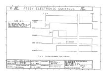
ABBEY ELECTRONIC CONTROLS M* NOTFS DEMAND--->. dtl = Settling Tine t 1 sec. t>t2 = Air Proving Oevice Reaction Tine dt3 s Safety Tine uithin uhich fl ane nust be detected to avoid lockout TITLE : - TIMING OtfiGRRM FOR FSC FX30xxx. NOTES < #> :-I** Ualue depends on appl ic ation. Dotted line shous alternative connection for Default High Fan use. ALL RESISTORS 0.25U 5V. ALL 2ENERS 0.5U ALL OIMENTIONS IN mm DIM'S TO 1DP = +0.1 mm „ DIM'S TO 20P = +0.02 mni ANGLES TO +/-0.5® SCALE = 100X UNLESS STATEO OTHERUlSEi
Open the catalog to page 12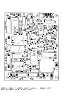
X030.L3 (Feb. 27, 1996) (13:25) (A.E.C.) SCALE: 150% Drill Ref Pnt: 0.034, 0.020 (inch)
Open the catalog to page 13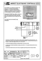
TCfflTCf CONTROLS_ Flame Probe Connection to the FX30SPT is via the special 10-way connector obtianable from Abbey Electronics. The board should be wired as shown above for Permanent Pilot application. The flame should be sensed on the pilot For direct burner ignition (DBI) use GV1 as the burner. For dual probe (separate spark/flame sensing) operation connect SR to earth. For single probe (combined spark/flame sensing) connect SR to FP. The spark electrode will thus sense flame as well. The OEM should observe all the normal rules and regulations governing electrical wiring and safety. MRTL ....
Open the catalog to page 14All Abbey Electronic Controls catalogs and technical brochures
 AEC
AEC1 Page
 WSX53
WSX534 Pages
 WSX53G06 PRECIPITATION
4 Pages
 WSX53B WEATHER SENSOR
4 Pages
 FX37FSA
1 Page
 WSX53A48 PRECIPITATION
4 Pages
 FX37-P16
1 Page
 WSX53A24 PRECIPITATION
4 Pages
 WSX53A12 PRECIPITATION
4 Pages
 WSX53A06 PRECIPITATION
4 Pages
 MPC34A DUAL MODE
2 Pages
 M021P MODULATING PUMP CONTROLLER
16 Pages
 WSX53
WSX534 Pages


- Bourn And Koch circuit breaker
- Bourn And Koch electronic filter
- Bourn And Koch waterproof pressure switch
- Gas pressure switch
- Bourn And Koch flow switch
- Differential pressure switch
- Current circuit breaker
- Air pressure switch
- Pump controller
- AC circuit breaker
- Manual reset circuit breaker
- Thermal circuit breaker
- Current amplifier
- IP66 pressure switch
- Active electronic filter
- Industrial flow switch
- High-pass electronic filter
- EMC filter
- Thermal flow switch