
- Catalogs
- ABB Smart Power
- Tmax UL/CSA Technical Catalog


- Company
- Products
- Catalogs
- News & Trends
- Exhibitions
Tmax UL/CSA Technical Catalog

Tmax UL/CSA Technical Catalog
Tmax T Generation circuit breakers are adaptable and versatile, supporting installations from 15 to 1200 A. They come in eight sizes with magnetic only, thermal magnetic, and electronic trip units, and a wide array of accessories. These breakers are designed for easy installation and advanced technology, providing high performance in compact sizes.
The Tmax family includes models T1, T2, Ts3, T3, T4, T5, T6, and T7, each offering unique features:
- T1, T2, T3: Compact sizes up to 225 A, with standardized accessories and innovative arc extinction technology.
- T4, T5, T6: High performance up to 800 A, with advanced electronics and a unified range of accessories.
- T7: Up to 1200 A, featuring advanced electronics, flexible installation options, and a new accessory wiring system.
A comprehensive range of accessories is available, including auxiliary contacts, undervoltage releases, shunt trips, terminal covers, and various terminal options. Conversion kits allow for easy adaptation between fixed, plug-in, and draw-out versions.
The document provides detailed interrupting ratings and trip unit options for each model, ensuring compatibility with various voltage and current requirements. The Tmax series supports both AC and DC applications, with specific ratings for different configurations.
Wiring diagrams are provided to facilitate installation and integration into existing systems, highlighting the modularity and flexibility of the Tmax series.
The dimensions of each Tmax model are optimized for space efficiency, with consistent depth across models to simplify switchboard integration. The Tmax series also features double insulation and positive operation indicators for enhanced safety.
The Tmax circuit breakers are designed with double insulation, positive operation indicators, and compliance with IEC and UL standards. They offer high degrees of protection and can operate in a wide temperature range, ensuring reliability in various environmental conditions.
The Tmax circuit breakers are designed to operate effectively up to an altitude of 6600 ft without performance changes. Above this altitude, performance derating is necessary due to changes in atmospheric properties. The rated service voltage and uninterrupted current decrease with increasing altitude.
The Tmax series features electromagnetic compatibility, ensuring protection operation without interference from electronic devices or atmospheric disturbances. The circuit breakers are tropicalized, tested for severe environmental conditions, and resistant to shock and vibration, complying with various international standards.
Tmax circuit breakers are available in fixed, plug-in, and draw-out versions, with manual or electric operation options. They can be installed in various positions without derating and are compatible with different switchboard types.
The Tmax series offers a range of accessories for ease of installation and flexibility. Accessories are harmonized across different models to reduce stock and enhance service flexibility.
The Tmax circuit breakers comply with UL, CSA, and IEC standards, and ABB's quality system is certified to ISO 9001. The environmental management system is certified to ISO 14001, and the health and safety management system to OHSAS 18001.
The Tmax series covers a range from 15 A to 1200 A with breaking capacities up to 150 kA at 480 VAC. Various trip units are available, including thermal magnetic and electronic options, suitable for both AC and DC applications.
The Tmax series is designed for interchangeability and flexibility, with options for motor protection and adjustable trip units. The series supports a wide range of applications, ensuring reliability and safety in power distribution.
The document provides detailed technical specifications and functionalities of various circuit breakers and their trip units, including thermal magnetic and electronic trip units. It outlines the types of trip units available, their applications, and the protection functions they offer.
Circuit breakers can be equipped with different types of trip units: TMF, TMD, TMA (thermal magnetic), MA (magnetic only), and electronic trip units like PR221DS, PR222DS/P, PR222DS/PD-A, PR231/P, PR232/P, PR331/P, and PR332/P. Each type offers specific protection features and is suitable for different current ranges.
The document lists the current ranges for various circuit breakers (T1, T2, T3, T4, T5, T6, T7) and their compatibility with different trip units. It also details the adjustable and fixed thresholds for thermal and magnetic protection.
The trip units provide several protection functions:
- L: Overload protection with inverse long-time delay.
- S: Short-circuit protection with time delay.
- I: Instantaneous short-circuit protection.
- G: Ground fault protection.
- Advanced Functions: Include protection against unbalanced phase, overtemperature, zone selectivity, voltage issues (undervoltage, overvoltage, residual voltage), reversal of power, and frequency variations.
These units offer high reliability and precision, are insensitive to temperature and electromagnetic interference, and are powered by current sensors. They include advanced protection functions and can be configured electronically or via dip switches.
The document emphasizes the ease of assembly and interchangeability of trip units, allowing end-users to adapt the circuit breakers to their specific needs, enhancing flexibility and cost efficiency.
The electronic trip units operate within a temperature range of -13 °F to +158 °F and a relative humidity of 98%. They comply with IEC 60947-2 standards for electromagnetic compatibility.
The document provides detailed technical specifications and functionalities of the PR332/P electronic trip unit and associated components used in power distribution circuit breakers. It covers warning and alarm indicators, data logging, trip information, load control, measurement functions, communication capabilities, and power supply requirements.
The front panel of the trip unit displays warnings and alarms through LEDs. Warnings include phase unbalance, overload pre-alarm, temperature threshold exceedance, contact wear, and phase rotation reversal. Alarms indicate timing of functions (L, S, G), higher temperature thresholds, contact wear, and reverse power flow protection.
The PR332/P includes a data logger that records instantaneous current and voltage values. Data can be downloaded using SD-Pocket or SD-TestBus2 applications for detailed fault analysis. It tracks up to 64 events with a maximum sampling rate of 4800 Hz.
In the event of a trip, the unit stores protection tripped data, opening data, and a timestamp. This information is accessible for 48 hours without auxiliary power and can be extended with a PR030/B battery unit or BT030 wireless communication unit.
The load control function prevents unnecessary trips by managing individual loads before overload protection is triggered. It requires an external PR021/K accessory unit and is active only with auxiliary power.
This optional module measures phase and neutral voltages, providing additional protections such as undervoltage, overvoltage, and frequency protections. It can energize the trip unit when line voltage exceeds 85 V.
The PR332/P measures phase and neutral currents, ground fault current, and displays them on a histogram. Additional measurements include voltage, power, power factor, frequency, and energy when the PR330/V module is connected.
The trip unit supports Modbus RTU protocol for data exchange with industrial devices. Communication modules like PR330/D-M and BT030 enable integration into networks and Bluetooth communication, respectively.
The unit is self-supplied from current sensors but can also operate with an auxiliary power supply. The PR330/V module can provide power when line voltage is above 85 V.
MCPs protect three-phase asynchronous motors using a combination of circuit breakers, thermal relays, and contactors. They offer magnetic and electronic trip units for short-circuit protection with adjustable thresholds.
The MCS are versatile devices used as circuit breakers in sub-switchboards, for switching and isolation of lines, busbars, or apparatus groups. They comply with UL 489 and CSA C22.2 standards, ensuring self-protection. Key specifications include:
- Types: Tmax T1N-D, T3S-D, Ts3H-D with ratings from 100A to 225A.
- Poles: Available in 3-4 pole configurations.
- Magnetic Override: Ranges from 1000A to 2250A.
- Rated Voltage: AC up to 600V, DC up to 600V.
These breakers, including Tmax T2, T4, and T5, are classified as UL Current Limiting, featuring peak current and specific let-through energy limitation. They are marked "Current Limiting" and have specific interrupting ratings:
- Frame sizes: 100A, 250A, 400A.
- Rated Voltage: AC up to 600V, DC up to 600V.
- Interrupting Ratings: Vary by voltage, with AC ratings up to 200 kA rms.
The document details various accessories and configurations for Tmax circuit breakers, including:
- Versions: Fixed, Plug-in, and Draw out, with conversion kits available for flexibility.
- Cradle: Allows for plug-in or draw out configurations, with options for front and rear terminals.
- Conversion Kits: Available for transforming fixed breakers into plug-in or draw out versions, including necessary components like isolating contacts and frames.
This document provides detailed specifications and instructions for the installation and use of circuit breakers, specifically focusing on the Tmax series. It includes information on accessories, connection terminals, and protective measures.
The document outlines the use of a special kit with a bellows for racking-out circuit breakers while the switchgear door remains closed. This kit is applicable to both fixed and draw-out versions, enhancing the versatility of residual current releases.
Various terminal types are available for different installation needs, including front terminals for copper cables and oriented rear terminals for switchboards with rear access. The document specifies the minimum and maximum cable cross-sections, types of cables, and torque values for terminal screws.
Terminal covers are used to prevent accidental contact with live parts, ensuring IP40 protection. Different covers are available for fixed and moving parts of circuit breakers.
These components enhance insulation between phases and are available in two heights. They are compatible with certain terminal types and can be mounted between adjacent circuit breakers.
Special kits are available for certain Tmax circuit breakers to facilitate auxiliary power supply connections directly from the terminals.
The document includes detailed tables specifying terminal types, compatible circuit breaker models, and installation configurations. It provides data on busbar and cable terminal dimensions, tightening torques, and compatibility with terminal covers and phase separators.
The document advises on ordering configurations for circuit breakers with mixed terminals and highlights the importance of using appropriate terminal covers and phase separators for safety and compliance with protection standards.
The document outlines the specifications for various types of terminals and accessories used with Tmax circuit breakers. It includes details on rear flat horizontal terminals for RC221/RC222, rear flat horizontal and vertical terminals for cradles, and rear spreaded terminals. The specifications cover dimensions, tightening torque, and the number of busbars or cable terminals that can be connected.
Installation procedures for service releases such as shunt trips, closing coils, and undervoltage releases are described. These components are mounted by pressing into designated slots on the circuit breaker and secured with screws. The document specifies the compatibility of these releases with different Tmax circuit breaker models.
The document references UL listings and IEC standards for various components, ensuring compliance with international safety and performance standards.
Recommendations include using class 8.8 screws for certain installations and ensuring proper tightening torque to maintain safety and functionality. The document also advises on the use of pre-cabled versions for certain applications to ensure ease of installation and reliability.
Details on accessories such as auxiliary contacts, shunt trip test units, and time delay devices for undervoltage releases are provided. The electrical characteristics of these components, including power consumption and operating voltage ranges, are specified to guide proper selection and use.
The tables provide critical data on dimensions, tightening torques, and electrical characteristics for various components. For example, the shunt trip's inrush power consumption is detailed across different voltage levels, and the auxiliary contacts' service current and breaking capacity are specified for different voltage categories.
Important information includes the compatibility of service releases with different Tmax models, the necessity of using specific screw classes for installation, and the electrical characteristics required for safe and effective operation of the circuit breakers and their accessories.
1. Current Ratings: AC/DC 24 V with ≥ 0.75 mA and 5 V with ≥ 1 mA.
2. Auxiliary Contacts: Various configurations available for different circuit breaker types (T1 to T7), with voltage ratings up to 400 V AC and 250 V AC/DC.
3. Insulation: System contact/ground insulation rated at 2000 V AC for 1 minute at 50 Hz, and contact/contact insulation at 400 V DC.
4. Mechanical Life: Up to 25,000 operations for certain models.
1. Assembly: Auxiliary contacts are mounted into special slots on the right side of the circuit breaker.
2. Testing: Testing extensions are available for Tmax T4, T5, and T6 circuit breakers to allow function tests in a safe position.
1. Compliance: Early auxiliary contacts comply with IEC 60204-1 and VDE 0113 standards.
1. Remote Control: Solenoid operators and motor operators are recommended for remote control and supervision of circuit breakers.
2. Adapters: Use specific adapters for pre-wired electrical accessories in plug-in or draw-out versions.
1. Voltage Ratings: Various configurations for AC and DC voltages, with specific ratings for different auxiliary contacts and motor operators.
2. Power Consumption: Inrush power consumption during operation is 1800 VA/1000 W, with standby power consumption < 100 mW.
3. Protection: Degree of protection on the front is IP30.
1. Control Impulse Time: Minimum control impulse time for opening and closing is >100 ms.
2. Mechanical Operation Counter: Available on motorized T7 to indicate the number of operations.
3. Spring Charging Motor: Automatically charges the circuit breaker operating mechanism springs for Tmax T7.
The document outlines the features and specifications of circuit breakers, particularly focusing on the Tmax series. It highlights the interlock mechanism that prevents simultaneous closing of two circuit breakers, available for both manual and motor-operated versions. The document also describes the transparent pushbutton protection (TCP) available in two versions for T7 circuit breakers, allowing for padlocking without hindering fault or remote command releases.
The Tmax series circuit breakers are compatible with residual current releases, ensuring protection against overloads, short-circuits, and ground fault currents. These releases comply with IEC 60947-2 appendix B and IEC 61000 standards, ensuring protection against unwarranted releases. They operate without auxiliary power, supplied directly by the network, and are effective even with limited phase supply.
The document details various residual current releases like RC221, RC222, RC211, RC212, and RC223, each designed for specific Tmax circuit breaker models. These releases offer features like trip coils, changeover contacts for trip signaling, and compatibility with electrical accessories. The RC223 release, for instance, is noted for its sensitivity to various fault current types and frequencies, making it suitable for industrial applications.
Installation procedures are simplified with direct cable connections to the circuit breaker. The document provides information on terminal kits and conversion kits for different configurations (fixed, plug-in, draw-out). It also mentions the availability of accessories like opening solenoids and brackets for DIN rail mounting.
Performance tables are included, detailing maximum withstand currents and compatibility with different circuit breaker sizes. The document emphasizes that a circuit breaker cannot simultaneously have a residual current release and a motor operator, except in specific configurations.
The SACE RCQ relay specifications include power supply voltage ranges, trip threshold adjustments, and pre-alarm threshold settings. It supports various toroidal transformers and provides signaling for alarm pre-thresholds and trip events.
The document outlines the specifications for various components and accessories related to SACE RCQ switchboard residual current relays and Tmax circuit breakers. The front and rear protection degrees are IP41 and IP30, respectively. The SACE RCQ relay is a type A residual current relay suitable for applications requiring coordinated residual current protection across distribution levels.
The SACE RCQ relay can be combined with Tmax circuit breakers and is installed externally on line conductors. It operates with thresholds up to 30 A trips and times up to 5 seconds. The relay acts on the circuit breaker release mechanism via shunt trip or undervoltage release.
Several accessories are detailed, including:
- Front Display Unit (FDU) for displaying settings and alarms.
- HMI030 interface for displaying trip unit measurements and alarms.
- Optional modules like PR330/V for voltage measurement and PR330/D-M for Modbus RTU communication.
- BT030 wireless communication unit for Bluetooth connectivity.
- PR030/B power supply unit for reading and configuring parameters.
- Trip unit adapters and rating plugs for modifying circuit breaker settings.
The document adheres to IEC standards for residual current releases and automatic transfer switches. It recommends using the SACE RCQ relay for applications requiring low sensitivity residual current protection and high sensitivity applications for protecting people against direct contacts.
The document includes tables listing the compatibility of various accessories with different trip units and circuit breakers. It also provides electrical characteristics for power contacts and details on connectors for external plant units or components.
Important parameters include the maximum changeover power, voltage, and current for power contacts, as well as the breaking capacity for resistive loads. The document emphasizes the need for specific connectors and modules for proper operation and communication within the system.
The document introduces the ATS010, a network-group switching device by ABB, designed for automatic management of switching procedures between normal and emergency power lines. It is compliant with various electromagnetic compatibility and environmental standards, ensuring reliability and ease of use in emergency power supply systems.
The ATS010 operates with a rated supply voltage of 24 V DC ± 20% or 48 V DC ±10%, with a maximum absorbed power of 5 W at 24 V DC and 10 W at 48 V DC. It functions within an operating temperature range of -25 °C to +70 °C and a maximum humidity of 90% without condensation. The device has a protection rating of IP54 for the front panel and dimensions of 144 x 144 x 85 mm.
The ATS010 manages the switching between normal and emergency lines by detecting errors in the mains voltage. It includes a built-in mains sensor and can handle networks with rated voltage up to 500 V AC. The device is equipped with safety systems for both software and hardware, including a watchdog system and an electrical interlock via power relay.
The device is suitable for various applications, including power supply for UPS units, hospital services, emergency power for civilian buildings, airports, hotels, data banks, telecommunications systems, and industrial lines for continuous processes.
The ATS010 is compatible with Tmax Ts3, T4, T5, T6, and T7 circuit breakers. It includes accessories such as motor operators, key locks, and status contacts. The document also details installation accessories like brackets for DIN rail fixing and flanges for compartment doors.
The document provides detailed technical information, including characteristic curves for trip units, temperature performance, and power losses. It includes examples of curve readouts for different circuit breakers and their respective trip curves for power distribution and motor protection.
This document provides technical specifications, trip curves, and wiring diagrams for various circuit breakers and their electronic trip units. It includes detailed information on the performance, functions, and configurations of these devices.
The document outlines the specifications for different models of circuit breakers, including T6 800, T7 1000/1200, and others. It details the current ratings, trip functions (L, S, I, G), and inhibition levels at various multiples of the nominal current (In).
Trip curves are provided for power distribution and motor protection. These curves illustrate the relationship between time (t) and current (I) for different trip units, showing how the breakers respond to overloads and short circuits.
The document includes tables showing the performance of circuit breakers at various ambient temperatures, indicating how the maximum current (Imax) changes with temperature.
Power loss data for different trip units and current ratings are provided, showing the power dissipation per pole for each configuration.
Detailed wiring diagrams are included for circuit breakers T1 through T7, showing the state of operation, version differences, and applications of various components like solenoid operators and motor operators.
The document describes the functions of different trip units, including overload protection, short-circuit protection, and ground fault protection. It also covers the applications of auxiliary units and signaling devices.
Critical parameters such as the let-through energy curves, limitation curves, and specific let-through energy for current limiting circuit breakers are highlighted.
This document provides detailed technical specifications and wiring diagrams for various types of circuit breakers and their components, including residual current releases, auxiliary contacts, and trip units. It outlines the functions and connections of each component, as well as compatibility and installation instructions.
- Residual Current Release (RC): Types RC221, RC222, and RC223 are mentioned, with contacts for electrical signaling of circuit breaker status and trip events.
- Pushbuttons and Contacts: Various pushbuttons (SC, SO, SO1, SO2, etc.) are used for opening and closing circuit breakers and starting or stopping motors.
- Current Transformers (TI): Placed on different phases and the neutral to monitor current flow.
- Connectors (X1, X2, XA, etc.): Used for interfacing with auxiliary circuits and electronic trip units.
- Trip Units (YO, YO1, YO2, YU): Include thermomagnetic and undervoltage releases for circuit protection.
- Fig. 1-6: Various types of opening and undervoltage releases.
- Fig. 7-12: Motor operators and signaling contacts.
- Fig. 21-32: Position contacts for circuit breaker status.
- Fig. 41-46: Auxiliary circuits for electronic trip units.
- Certain circuit combinations are incompatible and cannot be supplied simultaneously on the same circuit breaker.
- Notes provide additional information on installation, such as the need for external resistors or specific connectors.
- Zone Selectivity: Describes inputs and outputs for protection mechanisms, including G, S, and D protections, and their configurations with the PR332/P trip unit.
- Control Mechanisms: Details the closing and opening controls from the PR332/P electronic trip unit, including motor operations for charging closing springs and various pushbutton controls for circuit breaker operations.
- Auxiliary Contacts and Signaling: Lists various contacts for signaling circuit breaker status, such as open, closed, tripped, and ready to close, along with programmable contacts for overload signaling.
- Current Transformers and Sensors: Specifies the placement and function of current transformers and Rogowski coils for monitoring phases and neutral lines.
- Wiring Diagrams: Provides graphical representations of circuits for different operations, including motor circuits, shunt trips, undervoltage releases, and auxiliary circuits for PR331/P and PR332/P trip units.
- Incompatibilities: Lists circuit configurations that cannot be supplied simultaneously on the same circuit breaker.
- Notes and Standards: Includes important notes on installation, operation, and compliance with standards such as IEC 60950 and CEI 64-8.
Catalog excerpts

Technical catalog Tmax. T Generation Low voltage molded case circuit breakers up to 1200 A UL 489 and CSA C22.2 Standard
Open the catalog to page 1
Main characteristics 3 Characteristic curves and technical information Wiring diagrams
Open the catalog to page 2
T GENERA TMAX. ADAPTABILITY AND VERSATILITY. Tmax is freedom. Freedom now reaching up to 1200 A with the new Tmax T7 circuit breaker. There's a boundless and highly diversified world of differing types of installations, requirements, needs and problems from 15 to 1200 A. With the T Generation everything becomes simple and rational – eight sizes to find the solutions you're looking for. BE FREE TO SIZE ANY TYPE OF INSTALLATION IN AN IDEAL WAY AT ALL TIMES. Thanks to the eight sizes and a complete series of magnetic only, thermal magnetic and electronic trip units. Also a wide range of accessories...
Open the catalog to page 3
ATION This means there is more space there is for cabling and simpler installation. There is also a reduction in the dimensions of the switchboard. BE FREE TO RIDE THE MOST ADVANCED TECHNOLOGY. It is thanks to this technology that T Generation now offers performance levels that were previously out of the question in circuit breakers with these dimensions. There are also some exclusive technical solutions which only ABB can offer you, such as the brand new UL 489 supplement SE electronic trip units designed for the new Tmax T7 or the new rapid accessory fitting system. FREEDOM FOR TOTALLY SAFE...
Open the catalog to page 4
TMAX T1, T2, Ts3 AND T3. ALL SOLUTIONS PERFECTLY COORDINATED, UP TO 225 A. Tmax T1, T2, Ts3 and T3 – the four “little ones” of the Tmax family – were thought up from the beginning to work together. You can select functions and performances which until now could not be found in circuit breakers with these dimensions. Perfect up to 225 A. There are many characteristics common to the T1, T2 and T3 frames. The single depth 2.76" (70 mm) of the three frames makes installation truly simpler. The new arcing chambers are produced with a gasifying material and an innovative construction system allows...
Open the catalog to page 5
circuit breaker with the same performance (100 A – up to 50 kA at 240 VAC), the overall dimensions of the apparatus are notably smaller. TMAX T2. INTELLIGENCE AND HIGH PERFORMANCE IN THE PALM OF YOUR HAND. Tmax T2 is the only 100 A circuit breaker available with such high performances in such compact overall dimensions. A breaking capacity of 150 kA at 240 VAC can be achieved. Tmax T2 can also be fitted with a latest generation electronic trip unit. TMAX T3. 225 A IN A DEPTH OF 2.76" (70 MM) FOR THE FIRST TIME. Tmax T3 is the first circuit breaker which carries 225 A in considerably smaller overall...
Open the catalog to page 6
TMAX T4, T5 AND T6. BE FREE TO CHOOSE UP TO 800 A. Tmax T4, T5 and T6 are the molded case circuit breakers with the best performance/size ratio on the market. The possibilities are practically unlimited, thanks to their dedicated and specific ranges, advanced electronics, as well as a complete and standardized range of accessories. The top quality materials and innovative construction techniques used by ABB mean Tmax circuit breakers can guarantee truly exceptional performance. For example, T4 and T5 have an interrupting capacity up to 150 kA at 480 VAC.
Open the catalog to page 7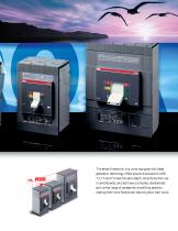
The series of electronic trip units, equipped with latest generation technology, offers solutions exclusive to ABB. T4, T5 and T6 have the same depth, simplifying their use in switchboards, and also have a complete, standardized and unified range of accessories, simplifying selection, making them more flexible and reducing stock item count.
Open the catalog to page 8
TMAX T7. FREEDOM TO THE NTH DEGREE. The new Tmax T7, available up to 1200 A either with a manual operating mechanism or motor operator, was conceived with a revolutionary design for circuit breakers of this type: advanced electronics, exceptional performance and new installation and accessory solutions. Additionally, cabling is facilitated by the reduced height. The new rapid accessory wiring system is great news. There are no loose wires inside the circuit breaker. Connection to the external circuit is rapid, simple and safe and no screws for terminating the external power supply cables are...
Open the catalog to page 9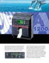
Special attention has been paid to the electronics and the results are the PR231, PR232, PR331 and PR332 new interchangeable electronic trip units, with modules and rating-plugs which can be replaced by the customer. The PR231 and PR232 trip units, with dip-switches for setting the protection thresholds, offer LEDs to signal tripping for each protection function: so the reason for circuit breaker tripping can always be easily found. The PR332 is decidedly ahead of its time fitted with a large graphic display, it allows all the information needed to be displayed simply and clearly. It also offers...
Open the catalog to page 10
Main characteristics
Open the catalog to page 12
Overview of the Tmax family MCCB Type Frame size Number of poles Rated voltage AC (50-60 Hz) DC 240 V AC 277 V AC 347 V AC 480 V AC 600Y/347 V AC 600 V AC 250 V DC (2 poles in series) 500 V DC (3 poles in series) 500 V DC (2 poles in series) 600 V DC (3 poles in series) [kA rms] [kA rms] [kA rms] [kA rms] [kA rms] [kA rms] [kA rms] [kA rms] [kA rms] [kA rms] TMF TMD/TMA MA Electronic PR221DS PR222DS/P PR222DS/PD-A PR231/P PR232/P PR331/P PR332/P H [in/mm] W 3p [in/mm] D [in/mm] [No. operations] Trip units Interrupting ratings T5 600 with electronic trip units only and in three pole version 2p...
Open the catalog to page 13
Construction characteristics Modularity of the series
Open the catalog to page 15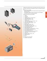
Starting from the xed version circuit breaker, all the other versions used for various requirements are obtained by means of mounting conversion kits. The following are available: – kit for converting a xed circuit breaker into the moving part of a plug-in and draw out one – circuit breaker cradles for plug-in and draw out circuit breakers – conversion kit for the connection terminals. Various accessories are also available: 1. Frame 2. Trip units 3. Front plate 4. Auxiliary contacts - AUX and AUX-E 5. Undervoltage release - UVR 6. Shunt trip - SOR and P-SOR 7. Terminal covers 8. Front for lever...
Open the catalog to page 16All ABB Smart Power catalogs and technical brochures
 ABB AbilityTM Smart Sensor
12 Pages
 Bus couplers
3 Pages
 SlimLine XR
52 Pages
 SACE Emax 2
277 Pages
 Rotary cam switches OC10...25
80 Pages
 TruOne
68 Pages
 Switch-disconnectors
192 Pages
 OFAM/ OFAA
2 Pages
 SACE Tmax XT
8 Pages
 YO-YC Test unit
5 Pages
 Case study. PRAMAC
4 Pages
 Installation contactors
32 Pages
 Softstarter PSR, PSE and PSTX
68 Pages
 SNK Series Terminal Blocks
8 Pages
 Blackburn Storm Safe
4 Pages
 Twist Tail Brochure
2 Pages
 PMA - Automation Products
24 Pages
 Superstrut SilverGalv
2 Pages
 ABB Elkay EasyDALI brochure
20 Pages
 Pacific Intertie
2 Pages
 ABB Division
17 Pages
 ABB HVDC Classic
24 Pages
 Switches for PV application
108 Pages
 V400
V4002 Pages
 V16
V162 Pages
 P42E
P42E2 Pages
 Nightstar
2 Pages
 ROYCE THOMPSON
4 Pages
 Guideway & Serenga 2
28 Pages
 Analog signal converters
28 Pages




Archived catalogs
 EasyLine XLP
31 Pages
 Switch fuses OS and OSM
116 Pages
 OC Cam Switches 10 to 25 Amperes
80 Pages
 SNK terminal blocks global catalog
236 Pages


- Hydraulic fitting
- Screw-in fitting
- Data connector
- Metal fitting
- Quick coupling
- Metal connector
- Elbow fitting
- Nickel-plated brass fitting
- Polymer connector
- Screw-in connector
- Industrial connector
- ABB cable sleeve
- Plastic fitting
- ABB cable gland
- ABB protection sleeve
- Push-in fitting
- Female fitting
- ABB waterproof cable gland