
- Catalogs
- ABB Smart Power
- SACE Tmax XT - New low voltage moulded-case circuit-breakers up to 250 A


- Company
- Products
- Catalogs
- News & Trends
- Exhibitions
SACE Tmax XT - New low voltage moulded-case circuit-breakers up to 250 A

SACE Tmax XT - New low voltage moulded-case circuit-breakers up to 250 A
The document is a technical catalogue for the SACE Tmax XT series of low voltage moulded-case circuit-breakers by ABB SACE, designed for up to 250A. It highlights the advanced features, versatility, and technological innovations of the product line.
The SACE Tmax XT series includes four frames: XT1, XT2, XT3, and XT4, with capacities ranging from 160A to 250A. These circuit-breakers are available in three-pole and four-pole versions, with fixed, plug-in, and withdrawable options. They feature the latest thermomagnetic and electronic trip units, offering interchangeability and high performance.
The circuit-breakers are designed with double insulation, positive operation, and electromagnetic compatibility. They can be installed in various positions without performance derating up to 2000m altitude. The devices operate in temperatures from -25°C to +70°C and offer different IP protection levels.
The Ekip trip units, part of the Tmax XT series, provide high reliability and precision. They include features like a continuous green LED for operation indication and a communication module for device interaction. Accessories such as the Ekip Display and Ekip LED Meter enhance usability.
The SACE Tmax XT circuit-breakers comply with IEC 60947-2 standards and various EC directives. They are certified by several naval registers and have a hologram for authenticity. ABB SACE's quality and environmental management systems are certified to ISO 9001, ISO 14001, OHSAS 18001, and SA 8000 standards.
The document provides detailed technical specifications, including rated service voltage, insulation voltage, breaking capacities, and mechanical and electrical life. It also outlines the dimensions and weight for different configurations.
The SACE Tmax XT series represents a significant advancement in circuit-breaker technology, offering extraordinary performance, versatility, and reliability for a wide range of applications.
The front label of the circuit-breaker includes key specifications such as rated current (In), rated impulse withstand voltage (Uimp), insulation voltage (Ui), short-circuit breaking capacities (Ics and Icu), and service voltage (Ue). It also references compliance with IEC 60947-2 and NEMA-AB1 standards.
The document categorizes trip units into magnetic, thermomagnetic, and electronic types, each with specific protection features. Magnetic trip units offer fixed or adjustable thresholds, while thermomagnetic units provide adjustable thermal and magnetic thresholds. Electronic trip units, such as the Ekip series, offer advanced protection functions for distribution networks, motors, and generators.
These devices are classified into instantaneous and selective types, with specific models like RC Inst and RC Sel 200 providing tailored protection features.
The SACE Tmax XT circuit-breakers are available in various models (XT1, XT2, XT3, XT4) with different rated currents and configurations. They are suitable for both AC and DC applications, with options for fixed, plug-in, and withdrawable versions.
The circuit-breakers are designed for optimal protection against overloads, short-circuits, and earth faults. They feature high let-through current peak and energy limiting characteristics, ensuring reliable operation in low voltage distribution networks.
These units, such as Ekip I and Ekip LS/I, offer adjustable protection thresholds and trip curves. They include features like LED indicators for status and alarms, manual settings via dip-switches, and test connectors for diagnostics.
The document highlights the suitability of SACE Tmax XT circuit-breakers for special applications, including 400Hz installations and communication systems, ensuring versatility across different installation requirements.
The document outlines the specifications for electrical accessories, particularly focusing on the connectors for circuit-breakers. It specifies that connectors for both fixed and moving parts are supplied with the MOE motor operator, as there is no dedicated code for the withdrawable version. The connectors must be installed on the right side of the circuit-breaker, allowing automatic disconnection of auxiliary circuits when the circuit-breaker is withdrawn.
The document describes two types of residual current circuit-breakers: 'mixed' and 'pure'. Mixed circuit-breakers provide protection against overloads, short-circuits, and earth fault currents, while pure circuit-breakers only offer residual current protection. These devices comply with IEC 60947-2 annex B and IEC 61000 standards.
The document provides a table listing residual current devices compatible with the Tmax XT family, detailing their configurations (fixed, plug-in, withdrawable) and features such as microprocessor technology, power supply, and connection options.
These releases are available for XT1, XT2, XT3, and XT4 circuit-breakers, with features like current setting, power-on LED, alarm signals, and test pushbuttons. The document explains conversion kits for changing fixed versions to plug-in or withdrawable types.
This release is used with XT3 circuit-breakers and is sensitive to various fault current types. It allows frequency band selection to suit different industrial requirements.
This device is suitable for installations with restrictive conditions and offers a wide range of settings for residual current protection. It requires an auxiliary power supply and can detect current leakage from 30mA to 30A.
The document describes accessories like the Ekip Display and Ekip LED Meter, which provide current values, alarms, and parameter programming. These accessories are compatible with various Ekip electronic trip units and offer features like self-supply mode and backlighting.
This document provides detailed technical specifications and descriptions of various accessories and components used in circuit-breakers and electronic trip units. It covers installation, compatibility, and functionality aspects of these components.
This device indicates the operational state of a circuit-breaker through different colored LEDs. It operates in self-supply mode and is compatible with certain front accessories but not with withdrawable breakers.
This interface device allows the Ekip M-LRIU to command a contactor. It can be installed on a DIN rail or door and is used with XT2-XT4 circuit-breakers for motor protection.
Designed for XT2 and XT4 circuit-breakers, this sensor reads neutral current for protection functions. It requires a specific connector for installation.
Various connectors are available for linking electronic trip units to external components, including connectors for auxiliary power supply and communication lines.
This interface, used with Ekip Com, provides a graphic display for viewing measurements and alarms. It supports Modbus and Local Bus communication.
Facilitates remote control of circuit-breakers and connects trip units to Modbus networks. It is available for fixed and withdrawable circuit-breakers.
Integrates SACE Tmax XT circuit-breakers into communication systems using various protocols like Profibus and DeviceNet.
A diagnostic tool for ABB SACE products, it simplifies the installation and troubleshooting of Modbus communication networks.
Used for supervising, configuring, and testing electronic protection trip units. It includes various components and software for comprehensive testing.
These Automatic Transfer Switches manage power line transfers to ensure continuous power supply. They offer advanced features like Modbus communication and priority line selection.
The document includes compatibility tables for accessories and outlines compliance with various standards for electronic equipment and environmental conditions.
This document provides technical specifications, installation procedures, and wiring diagrams for the Tmax XT4 circuit-breakers and their accessories. It includes detailed drilling templates, terminal configurations, and wiring instructions for various configurations and versions of the circuit-breakers.
- Drilling Templates: Detailed templates for doors with direct rotary handles, with and without flanges, and for circuit-breaker fixing on sheets.
- Overall Dimensions: Dimensions for Tmax XT4 accessories and installations, including plug-in and withdrawable circuit-breakers.
- Terminals: Information on various terminal types such as EF, ES, MC, and HR/VR, including fixing distances and insulating barriers.
- Fixing Instructions: Guidelines for fixing circuit-breakers at specified distances with or without flanges.
- Insulating Distances: Minimum center distances for installation in metallic cubicles, ensuring safety and compliance with voltage requirements.
- Reading Instructions: Diagrams are provided for fixed, plug-in, and withdrawable versions, showing state of operation and auxiliary circuit connections.
- Graphic Symbols: Symbols used in diagrams are based on IEC 60617 and CEI standards, covering various components like contacts, transformers, and relays.
- Specific Configurations: Diagrams for different circuit-breaker configurations, including those with thermomagnetic and electronic trip units.
- Insulating Barriers: Use of compulsory insulating barriers between phases to ensure safety.
- Adaptor Requirements: Certain configurations require adaptors that are not provided and must be sourced separately.
- Mandatory Components: Insulated plates and barriers are compulsory for certain voltage levels and configurations.
- Optional Accessories: Terminal covers with IP40 protection and key locks are available as optional accessories.
The document provides detailed wiring diagrams for various electronic trip units such as Ekip LSI, Ekip LSIG, and Ekip M-LRIU. These units are connected with display units like Ekip Display or Ekip LED Meter. The diagrams illustrate auxiliary circuits and connections with interface units like Ekip Com and HMI030, highlighting components such as current transformers, opening solenoids, and connectors.
The document emphasizes compliance with standards like IEC 60950 and UL 1950 for galvanically separated converters, ensuring leakage currents do not exceed 3.5 mA. It also references standards IEC 60364-41 and CEI 64-8 for electrical installations.
Instructions for resetting circuit-breakers after tripping are provided, with options for manual and electrical resetting. The document advises on wiring requirements and emphasizes the need to identify the cause of tripping before resetting.
The document includes ordering codes for circuit-breakers and accessories across different models (XT1, XT2, XT3, XT4). It provides examples of ordering configurations, specifying terminal types and installation kits.
- Electronic Trip Units: Ekip LSI, LSIG, M-LRIU
- Interface Units: Ekip Com, HMI030
- Actuator Units: MOE-E for stored energy motor operators
- Connectors: Various types for auxiliary contacts and circuit-breaker applications
- Current Transformers: Placed on phases L1, L2, L3, and neutral
The document includes notes on the use of insulated auxiliary power (Uaux) and the importance of using appropriate converters to prevent excessive leakage currents.
This document provides detailed ordering codes and specifications for XT2 circuit-breakers and their accessories. It includes information on thermomagnetic and electronic trip units, as well as various accessories for installation and operation.
- XT2 Circuit-Breakers: Available in different configurations such as fixed, plug-in, and withdrawable types with 3 or 4 poles. They feature thermomagnetic (TMA, TMG, MA) and electronic (Ekip LS/I, Ekip I, Ekip LSI, Ekip LSIG, Ekip M-I) trip units.
- Breaking Capacity: The circuit-breakers have different breaking capacities (Icu) at 415V, ranging from 36kA to 150kA.
- Thermomagnetic Units: Include TMA, TMG, and MA types with various current ratings.
- Electronic Units: Include Ekip LS/I, Ekip I, Ekip LSI, Ekip LSIG, Ekip M-I, and others, each with specific current ratings and configurations.
- Fixed Parts and Conversion Kits: Kits available for converting fixed parts to plug-in or withdrawable types, including terminal adapters and conversion kits.
- Service Releases: Shunt opening releases (SOR), undervoltage releases (UVR), and their cabled versions are available for different voltage ranges.
- Connectors: Include socket-plug connectors for panels and fixed parts.
- Electrical Signals: Auxiliary contacts (AUX) and auxiliary position contacts (AUP) for signaling and control.
- Motor Operators: Stored energy motor operators (MOE) and electronic versions (MOE-E) for various voltage ranges.
- Rotary Handles: Various types of rotary handles for direct and transmitted operation, including emergency versions.
- Locks: Key locks and padlocks for securing circuit-breakers in open or closed positions.
- Voltage Ratings: Accessories and releases are available for a wide range of AC/DC voltages.
- Installation Options: Multiple configurations for installation, including front terminals and rear terminals.
The document serves as a comprehensive guide for selecting and ordering XT2 circuit-breakers and their accessories, providing detailed specifications and options for customization based on application needs.
This section details various key lock configurations for different components such as circuit breakers, handles, and motors. The KLC Ronis key locks are available in different types (A, B, C, D) and can be removed in open or both positions. RHL Ronis key locks are specified for handles with options for different or same keys. Mechanical interlocks are also listed with specific types like MIR-H and MIR-V.
Residual current devices (RCDs) are categorized by poles and types, including RC Inst and RC Sel. Panel type residual current relays are available for different voltage ranges, and toroids are specified by diameter for installation.
Installation components include brackets for DIN rail fixing, insulating terminal covers, and phase separators. Terminals are available in various configurations, including front, extended front, and multi-cable terminals. Accessories for electronic trip units and motor operators are also detailed.
The document provides extensive ordering codes for XT2 and XT3 circuit breakers and accessories. This includes thermomagnetic trip units, switch-disconnectors, and conversion kits for fixed and plug-in parts. Shunt opening releases, undervoltage releases, and auxiliary contacts are specified with both cabled and uncabled versions.
Automatic transfer devices (ATS021 and ATS022) are listed with their respective codes. Spare parts for residual current devices and other components are also included, ensuring comprehensive coverage of replacement needs.
This document provides detailed specifications and ordering codes for XT4 circuit-breakers and associated components, including auxiliary contacts, flanges, and trip units. It is intended for use in electrical systems requiring precise circuit protection and control.
- XT4 Circuit-Breakers: Available in various configurations including 3 poles and 4 poles, with fixed front terminals. They feature thermomagnetic and electronic trip units with different interrupting capacities (Icu) ranging from 36kA to 150kA at 415V.
- Trip Units: Multiple types are available, including TMD/TMA, MA, Ekip LS/I, Ekip I, Ekip LSI, Ekip LSIG, and Ekip E-LSIG, each with specific current ratings and functionalities.
- Flanges: Different sizes and types are provided for circuit-breakers, MOD, direct handle, and residual current devices.
- Ordering Codes: Each component and configuration has a unique ordering code for easy identification and procurement.
- Conversion Kits: Kits are available to convert fixed circuit-breakers into plug-in or withdrawable types, enhancing flexibility in installation and maintenance.
- Auxiliary Contacts: Options include loose uncabled and cabled contacts for different voltage ratings.
- Service Releases: Shunt opening releases (SOR) and undervoltage releases (UVR) are available in both cabled and uncabled versions, supporting various voltage ranges.
- Key Locks/Padlocks: Security features for fixed parts, including Ronis key locks, are provided to ensure safety and control.
- Ensure compatibility of components with existing systems by verifying ordering codes and specifications.
- Consider using conversion kits for future-proofing installations, allowing for easy upgrades and maintenance.
The document provides detailed specifications and ordering codes for various electrical components and accessories, primarily focusing on circuit-breakers and related devices. It includes information on uncabled and cabled versions of undervoltage releases, auxiliary contacts, motor operators, rotary handles, locks, residual current devices, terminals, and more.
1. Rated Service Voltage (Ue): Determines device usage and applicable tests.
2. Rated Insulation Voltage (Ui): Voltage for dielectric tests; service voltage cannot exceed this.
3. Rated Impulse Withstand Voltage (Uimp): Peak impulse voltage the device can withstand.
4. Rated Ultimate Short-Circuit Breaking Capacity (Icu): Maximum short-circuit current a circuit-breaker can break twice.
5. Rated Service Short-Circuit Breaking Capacity (Ics): Current a circuit-breaker can break three times and still carry rated current.
6. Rated Short-Time Withstand Current (Icw): Current a circuit-breaker can carry for a short time under specified conditions.
7. Rated Short-Circuit Making Capacity (Icm): Maximum peak current a device can handle.
8. Utilisation Categories: Defines circuit-breaker design for selectivity and short-circuit conditions.
1. Electrical and Mechanical Life: Number of cycles a device can perform under load and no-load conditions.
2. Dissipated Power: Energy loss due to electrical resistance.
3. Utilisation Categories for Operating Parts: Standard categories for controlling various loads.
1. Release: Device that allows opening/closing of operating devices.
2. Thermomagnetic and Magnetic Trip Units: Protect against overloads and short-circuits.
3. Electronic Trip Unit: Uses current transformers for protection, suitable for AC networks.
4. Residual Current Release: Detects earth fault currents.
5. Protection Types: Includes magnetic, thermal, overload, short-circuit, and earth fault protections.
1. TT, TN, and IT Systems: Different earthing systems and their configurations.
1. Phase Unbalance and Phase Loss Protection: Detects current unbalance.
2. Rotor Lock Protection: Protects motor from rotor stopping damage.
3. Starting Current and Time: Current and time required for motor startup.
4. Operating Class: Defines thermal relay trip curves.
1. Communication Protocol: Standardized dialogue among digital devices.
2. Modbus RS485: Common protocol in industrial automation.
The document describes the data transmission and reception points as nodes, with communication lines being the physical means (such as coaxial cables, twisted telephone cables, optic fibers, or infrared rays) that connect these nodes and allow data transfer.
The bus network structure utilizes a common transmitting medium, typically a twisted or coaxial cable, to connect all nodes in parallel. For more details, reference is made to QT9: “Communication with ABB circuit-breakers via Bus.”
- Standards: Technical specifications approved by recognized organizations to define product or service characteristics.
- Directive: Rules defining essential safety requirements for products to ensure user safety.
- Naval Register: Certification body for products/services conforming to International Maritime Organization regulations.
- RoHS Directive: European directive aimed at reducing hazardous substances in electrical and electronic equipment.
- CE Marking: A mark indicating conformity with essential requirements for marketing in the European Union.
The document provides a glossary of symbols used in circuit-breaker documentation, including abbreviations for various components and configurations such as circuit-breakers, terminals, handles, and auxiliary contacts.
Technical documentation is available online, covering topics such as low voltage selectivity, transformer substations, distribution systems, circuit-breakers, and power factor correction. The documentation is accessible on the ABB BOL website.
Contact details for ABB SACE, a division of ABB S.p.A., are provided, including address, phone, and fax numbers.
Catalog excerpts

The data and illustrations are not binding. We reserve the right to make changes in the course of technical development of the product. Copyright 2011 ABB. All rights reserved. SACE Tmax XT. New low voltage moulded-case circuit-breakers up to 250 A ABB SACE A division of ABB S.p.A. L.V. Breakers Via Baioni, 35 24123 Bergamo – Italy Phone: +39 035 395 111 Fax: +39 035 395 306-433 Technical catalogue - Preliminary SACE Tmax XT New low voltage moulded-case circuit-breakers up to 250 A
Open the catalog to page 1
The SACE Tmax XT Ranges 2
Open the catalog to page 3
New SACE Tmax XT. Simply XTraordinary. ABB SACE is proud to present you the result of a long and intense research and development project: the new SACE Tmax XT up to 250A - ABB SACE’s new family of moulded-case circuit-breakers.
Open the catalog to page 4
Today a highly advanced range of circuit-breakers has been brought out, with unparalleled versatility of use and able to solve all installation problems brilliantly. You can find the new SACE Tmax XT in the three-pole and four-pole, fixed, plug-in and withdrawable versions, fitted with the very latest generation thermomagnetic and electronic trip units, with the possibility of interchangeability. The new SACE Tmax XT set up a new technological standard and leave you free to think up and build installations with extraordinary performances. An extraordinary demonstration of ABB SACE’s innovation...
Open the catalog to page 5
New SACE Tmax XT. XTraordinary completeness of range. Here are the 4 new SACE Tmax XT frames for you: – the small XT1 up to 160A; – the high-performing XT2 up to 160A; – the reliable XT3 up to 250A; – the powerful XT4 up to 250A.
Open the catalog to page 6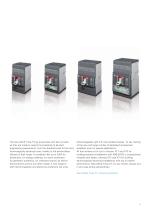
The new SACE Tmax XT go everywhere and fear no tests as they are made to respond successfully to all plant engineering requirements, from the standard ones to the most technologically advanced ones, thanks to the extraordinary fullness of their range. A complete offer up to 250A for distribution, for energy metering, for motor protection, for generator protection, for oversized neutral, as switchdisconnectors and for any other needs. A new range of both thermomagnetic and electronic protection trip units, interchangeable right from the smallest frames. To say nothing of the new and large number...
Open the catalog to page 7
New SACE Tmax XT. XTraordinary advanced electronics. Welcome a totally renewed, high-performing and versatile range of electronic trip units. Ekip: this is the name of the new, very latest generation electronic trip units which equip the new frames of SACE Tmax XT2 and SACE Tmax XT4 circuit-breakers.
Open the catalog to page 8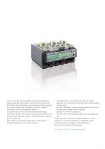
The trip units are interchangeable and guarantee absolute tripping reliability and precision. Apart from the continuous green LED, which indicates correct operation of the protection trip unit, all the Ekip trip units also have a LED to signal intervention of all the protection functions. To allow the Ekip units to communicate and exchange information with the other devices, simply insert the Ekip Com module inside the circuit-breaker, leaving the space inside the electric panel free. All the Ekip trip units can be fitted with a vast range of dedicated accessories. The main ones are: – the Ekip...
Open the catalog to page 9
Construction Characteristics
Open the catalog to page 11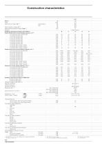
Construction characteristics XT1 Size(G2.1) Poles Rated service voltage, Ue(G2.4) 90kA@690V only for XT4 160. Available shortly, please ask ABB SACE XT1 plug-in In max=125A [No. Operations] [No. Hourly operations] [No. Operations] [No. Hourly operations] [mm] Total opening time Circuit-breaker with shunt opening release Circuit-breaker with undervoltage release Trip units for power distribution TMD/TMA TMD Ekip LS/I Ekip I Ekip LSI Ekip LSIG Ekip E Trip units for motor protection MF/MA Ekip M-I Ekip M-LIU Ekip M-LRIU Trip units for generator protection TMG Ekip G-LS/I Trip units for oversized...
Open the catalog to page 12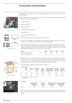
Construction characteristics Positive operation Installation positions The references in round brackets <s"> in the technical catalogue refer to the Glossary in the final charter of the technical catalogue. All the moulded-case circuit-breakers in the SACE Tmax XT family are realized in accordance with the following construction characteristics: power supply from the top towards the bottom or vice versa; versatility of the installation. It is possible to mount the circuit-breaker in horizontal, vertical, or lying down position without any derating of the rated characteristics; no nominal performance...
Open the catalog to page 14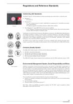
Regulations and Reference Standards Conformity with Standards The SACE Tmax XT circuit-breakers and their accessories are constructed in conformity with: Standard(G6.1): – IEC 60947-2; Directives(G6.2): – EC “Low Voltage Directive” (LVD) N° 2006/95/EC (in replacement of 73/23/EEC and subsequent amendments); – EC “Electromagnetic Compatibility Directive” (EMC) 2004/108/CE; Naval Registers(G6.3) (ask ABB SACE for the versions available): – Lloyd’s Register of Shipping, Germanischer Lloyd, Bureau Veritas, Rina, Det Norske Veritas, Russian Maritime Register of Shipping, ABS. Certication of conformity...
Open the catalog to page 15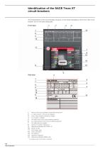
Identification of the SACE Tmax XT The characteristics of the circuit-breaker are given on the rating nameplate on the front of the circuit- breaker, and on the side rating plate. Front label Side label 1 Name of the circuit-breaker and performance level1" 3 Uimp: rated impulse withstand voltage1" 5 Ics rated short-circuit duty breaking capacity1" 6 leu: rated ultimate short-circuit breaking capacity1" "I In compliance with the I EC 60947-2 Standard
Open the catalog to page 16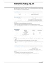
Nomenclature of the trip units and residual current protection devices The tables below give details of the logic with which each thermomagnetic trip units, electronic trip units and residual current devices has been named. Magnetic trip units Family Name F: with fixed threshold A: with adjustable threshold Family Name A: with adjustable thermal and magnetic threshold D: with adjustable thermal and fixed magnetic threshold G: with adjustable thermal and fixed magnetic threshold (for generator protection) Thermomagnetic trip units Example: MA: magnetic only trip unit, with adjustable protection...
Open the catalog to page 17All ABB Smart Power catalogs and technical brochures
 ABB AbilityTM Smart Sensor
12 Pages
 Bus couplers
3 Pages
 SlimLine XR
52 Pages
 SACE Emax 2
277 Pages
 Rotary cam switches OC10...25
80 Pages
 TruOne
68 Pages
 Switch-disconnectors
192 Pages
 OFAM/ OFAA
2 Pages
 SACE Tmax XT
8 Pages
 YO-YC Test unit
5 Pages
 Case study. PRAMAC
4 Pages
 Installation contactors
32 Pages
 Softstarter PSR, PSE and PSTX
68 Pages
 SNK Series Terminal Blocks
8 Pages
 Blackburn Storm Safe
4 Pages
 Twist Tail Brochure
2 Pages
 PMA - Automation Products
24 Pages
 Superstrut SilverGalv
2 Pages
 ABB Elkay EasyDALI brochure
20 Pages
 Pacific Intertie
2 Pages
 ABB Division
17 Pages
 ABB HVDC Classic
24 Pages
 Switches for PV application
108 Pages
 V400
V4002 Pages
 V16
V162 Pages
 P42E
P42E2 Pages
 Nightstar
2 Pages
 ROYCE THOMPSON
4 Pages
 Guideway & Serenga 2
28 Pages
 Analog signal converters
28 Pages




Archived catalogs
 EasyLine XLP
31 Pages
 Tmax UL/CSA Technical Catalog
288 Pages
 Switch fuses OS and OSM
116 Pages
 OC Cam Switches 10 to 25 Amperes
80 Pages
 SNK terminal blocks global catalog
236 Pages


- ABB fitting
- Hydraulic fitting
- Screw-in fitting
- Data connector
- Metal fitting
- Quick coupling
- Metal connector
- Elbow fitting
- Nickel-plated brass fitting
- Polymer connector
- Screw-in connector
- Industrial connector
- ABB cable sleeve
- Plastic fitting
- ABB cable gland
- ABB protection sleeve
- Push-in fitting
- ABB waterproof cable gland
- Female fitting