Catalog excerpts
InLine II - ZUBM/ZLBM/ZHBM Fuse Switch Disconnectors
Open the catalog to page 1
Technical Data Cable terminations and cable shrouds Ordering tables proE power switchboards Dimensional drawings
Open the catalog to page 3
Fusible protection Safe, reliable and cost efficient solution The InLine II fuse switch disconnector fulfils the highest requirements for modern switch fuses with a total safety concept. The fuse switches are tested according to the EN/IEC 60947-3 standard, meeting all the requirements for isolation, current making, performance and safety. Selectivity The melting curves and current limiting diagrams for NH fuse links are given in the EN/IEC 60269-2 standard. The s tandardised fuse characteristics and high degree of current limitation ensure a simple and effective co-ordination with fuse ...
Open the catalog to page 4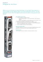
InLine II Designed for the future ABB is proud to introduce the latest technology of Fuse Switch Disconnectors to ensure stability and the highest safety in the power distribution network. The new generation InLine II offers the highest level of personal safety during operation and service. Save installation time and costs • InLine II is available in two different versions: - ZLBM with reduced depth (121 mm) for space saving in Cable Distribution Cabinets - ZHBM for easy integration of current transformers at the back (depth 154 mm). The dimensions are equivalent to similar products in the...
Open the catalog to page 5
InLine II Designed for the future Features −− Available as 160A, 250A, 400A and 630A types in combination with NH/DIN HRC Fuse Links according to EN/ IEC 60269 −− Type tested in accordance to EN/IEC 60947-3 −− 1 - pole and 3 - pole variants −− For vertical and horizontal installations −− Designed for 185mm busbar distance −− IP30 degree of protection from the front - Padlocking in open and closed position at the 3-pole version - Padlocking in closed position at the 1-pole version −− Park position with possible padlocking at the 1 - pole type −− Sealing solutions −− Wide range of...
Open the catalog to page 6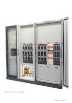
InLine II in proE power switchboard
Open the catalog to page 7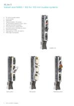
InLine II Variant size NH00 / 160 for 100 mm busbar systems For 100 mm busbar systems 3 pole operated Parkposition Padlock possibilty in ON position AC 23B breaking capacity at 160 A / 500 V 3xM8 terminal bolts as standard IP 30 at the front in closed position Symmetric body for terminals up or down Cable shroud included Type tested acc. to EN / IEC 60947-3 Wide range of accessories Open position Park position
Open the catalog to page 8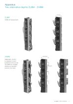
Apparatus Two alternative depths ZLBM - ZHBM ZLBM ZLBM with reduced depth. ZHBM depth, +32,5mm for integration of current transformers at the rear side. The ZHBM has compatible dimensions to equivalent
Open the catalog to page 11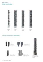
Apparatus Fuse rails ZUBM Phase barriers and cable shrouds are available separately Phase barrier kit for ZUBM00 Fuse rail Cable shroud for ZUBM00 Fuse rail Phase barrier kit for ZUBM123 Fuse rail Cable shroud for ZUBM123 Fuse rail Fuse protection covers carried by phase barriers
Open the catalog to page 12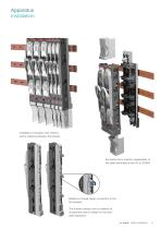
Apparatus Installation Installation at busbars with 185mm centre distance between the phases Symmetric front position independent of the cable terminations are UP or DOWN Bolted or hooked clamp connection to the flat busbars. The hooked clamps can be ordered as accessories and be added on the standard apparatus. In Line II | 1SEC312022B0202
Open the catalog to page 13
Apparatus Operation ZLBM - ZHBM 1-pole ON - Closed position Replacement of fuses position Replacement of fuses position ZLBM - ZHBM 3-pole ON - Closed position
Open the catalog to page 14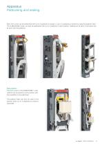
Apparatus Padlocking and sealing Each front cover can be padlocked with up to 2 padlocks pr phase, or up to 3 padlocks pr phase by using the padlock hasp. The ZLBM/ZHBM 3–pole, can also be padlocked with up to 2 padlocks in open position. Sealing can be done in the same way as done with the padlocks. Park position The front covers of the ZLBM/ZHBM 1-pole variants can be placed in park position with the possibility to be padlocked. The padlock hasp can also be used in this position when up to 3 padlocks pr phase is requested.
Open the catalog to page 15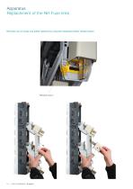
Apparatus Replacement of the NH Fuse links NH fuses can be easily and safely replaced by using the integrated yellow release button Release button
Open the catalog to page 16
Apparatus Cable terminations Universal terminal bolts The ZLBM/ZHBM 123 are delivered with standing M12 bolts at the cable terminals as standard. However, if the demand is to insert the M12 bolt from the front, the nut and the bolt can easily be exchanged as shown below: Standing bolt Integrated terminal V-clamps The ZLBM/ZHBM 00/123 can be delivered with integrated V-clamps
Open the catalog to page 17
Apparatus Properties Voltage measurement The front windows can be slided up to give access for voltage measuserement at the fuse contacts Optimized ventilation ribs The design of the ZLBM/ZHBM body has been given priority to give the most optimized ventilation of the apparatus. An integrated ventilation channel at the side of the body will also support the air ventilation upwards between the apparatuses when they are installed side by side. Circuit labels The integrated front terminal shroud has a dedicated area for circuit labels. This integrated front terminal shroud is interlocked when...
Open the catalog to page 18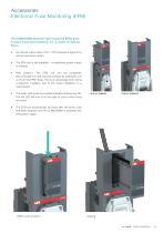
Accessories Electronic Fuse Monitoring (EFM) The ZLBM/ZHBM electronic fuse monitoring (EFM) gives an alarm if any fault conditions, if 1, 2, and/or 3 fuses are blown. • An internal output relay (1NC + 1NO) ensures a signal for a remote fuse blown alarm. The EFM unit is self supplied - no additional power supply is required. Park position: The EFM unit can be completely disconnected from the live fuse contacts by pulling the unit out from the EFM house. This is an advantage when doing a dielectric insulation test of the whole installation in a switchboard. The green LED in the front panel...
Open the catalog to page 19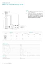
Accessories Electronic Fuse Monitoring (EFM) Note • The EFM requires power supply from the busbar side phase L2 and L3. • If there is a loss of the power supply voltage after a blown fuse alarm is created, there must be a minimum period of 10 seconds before the power supply can be connected again. This is to ensure correct alarm positioning of the EFM relay. Q1= Fuse switch disconnector K1= Fuse monitor (EFM) V1= Fuses ok V2= Fuse(s) blown X1= Multiplug terminals Fuse status 1. Closed Fuses blown Fuses blown EFM Technical data Minimum operating voltage Maximum operating voltage Uimp. over a...
Open the catalog to page 20All ABB Smart Power catalogs and technical brochures
-
ABB AbilityTM Smart Sensor
12 Pages
-
Bus couplers
3 Pages
-
SlimLine XR
52 Pages
-
SACE Emax 2
277 Pages
-
Rotary cam switches OC10...25
80 Pages
-
TruOne
68 Pages
-
Switch-disconnectors
192 Pages
-
OFAM/ OFAA
2 Pages
-
SACE Tmax XT
8 Pages
-
YO-YC Test unit
5 Pages
-
Case study. PRAMAC
4 Pages
-
Installation contactors
32 Pages
-
Softstarter PSR, PSE and PSTX
68 Pages
-
SNK Series Terminal Blocks
8 Pages
-
Blackburn Storm Safe
4 Pages
-
Twist Tail Brochure
2 Pages
-
PMA - Automation Products
24 Pages
-
Superstrut SilverGalv
2 Pages
-
ABB Elkay EasyDALI brochure
20 Pages
-
Pacific Intertie
2 Pages
-
ABB Division
17 Pages
-
ABB HVDC Classic
24 Pages
-
Switches for PV application
108 Pages
-
V400
2 Pages
-
V16
2 Pages
-
P42E
2 Pages
-
Nightstar
2 Pages
-
ROYCE THOMPSON
4 Pages
-
Guideway & Serenga 2
28 Pages
-
Analog signal converters
28 Pages
-
Switch fuses OS and OSM
116 Pages
-
SNK terminal blocks global catalog
236 Pages
-
OC Cam Switches 10 to 25 Amperes
80 Pages
-
EasyLine XLP
31 Pages
-
Tmax UL/CSA Technical Catalog
288 Pages


