- Catalogs
- ABB Smart Power
- Automatic control units, OMD200 and OMD300
- Company
- Products
- Catalogs
- News & Trends
- Exhibitions
Automatic control units, OMD200 and OMD300
1 /48Pages

Automatic control units, OMD200 and OMD300
1 /48Pages
Catalog excerpts
Automatic control units, OMD200 and 300 Installation and operating instructions Power and productivity
Open the catalog to page 1
Installation and operating instructions, OMD200 and OMD300
Open the catalog to page 3
Installation and operating instructions, OMD200 and OMD300
Open the catalog to page 4
Installation and operating instructions, OMD200 and OMD300 1. Introduction This manual describes the installation and the basic operation of the OMD200 and OMD300 automatic control units. The instructive part is followed by a section on available accessories. 1.1 Use of symbols Hazardous voltage: warns about a situation where a hazardous voltage may cause physical injury to a person or damage to equipment. General warning: warns about a situation where something other than electrical equipment may cause physical injury to a person or damage to equipment. Caution: provides important information...
Open the catalog to page 5
Installation and operating instructions, OMD200 and OMD300 2. Product overview The automatic transfer switch concept is applied to any application requiring switching from the primary power line to secondary power line to ensure the supply of loads. OMD200: Analysing the voltage, frequency and the phase balance. Includes the generator START / STOP command. OMD200 has two sensors to monitor two three-phase power lines, both able to work with single phase, too. It has the capability to monitor two power supply lines and to manage a single change-over switch. With DIP-switches it can be chosen whether...
Open the catalog to page 6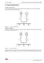
Installation and operating instructions, OMD200 and OMD300 2.1 Typical applications A. Mains - Generator line In case of loss of the primary power line, the OMD_ device manages the switching to the emergency power line equipped with a genset system. Mains - Generator line B. Mains a – Mains b In case of loss of the primary power line, the OMD_ device manages the switching to a secondary power line used as an emergency source. Automatic control unit type OMD_ is designed for single and three-phase distribution systems in diverse applications. OMD_ is supplied from Line 1 and Line 2 and can be...
Open the catalog to page 7
Installation and operating instructions, OMD200 and OMD300 Automatic control units OMD_ have the capability to monitor two three-phase power lines, both able to also work with single phase. With DIP switches, it can be chosen whether or not the N-line is connected. If OMD_ is used without the N-line, the external transformer must be used. LINE 1 L1 L2 L3 1 L1 2 L2 X11 LN1 3 L3 4 If OMD_ is used without the N-line, the external transformer must be used.
Open the catalog to page 8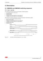
Installation and operating instructions, OMD200 and OMD300 3. Description 3.1 OMD200 and OMD300 switching sequence 3.1.1 Line 1 priority The switching sequence can be summarized in following steps: An anomaly occurs on the Line 1 Switching delay Generator start Change-over switch (Switch I) to the position O Change-over switch (Switch II) to the position II And the back switching sequence can be summarized in the following steps: The Line 1 will start the normal functioning Back switching delay Change-over switch (Switch II) to the position O Change-over switch (Switch I) to the position I Generator...
Open the catalog to page 9
Installation and operating instructions, OMD200 and OMD300 3.1.2 No line priority The switching sequence can be summarized in following steps: An anomaly occurs on the Line 1 Switching delay Generator start Change-over switch (Switch I) to the position O Change-over switch (Switch II) to the position II And the back switching sequence can be summarized in the following steps: The Line 1 will start the normal functioning Change-over switch stays in position II An anomaly occurs on the Line 2 Back switching delay Change-over switch (Switch II) to the position O Change-over switch (Switch I) to...
Open the catalog to page 10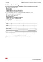
3. Description Installation and operating instructions, OMD200 and OMD300 3.1.3 Manual back switching mode The switching sequence of OMD200 and OMD300 can be summarized in following steps: ► An anomaly occurs on the Line 1 ► Switching delay ► Change-over switch (Switch I) to the position O ► Change-over switch (Switch II) to the position II And the back switching sequence can be summarized in the following steps: ► The Line 1 will start the normal functioning ► Change-over switch stays in position II ► An anomaly occurs on the Line 2 ► Back switching delay ► Change-over switch (Switch II)...
Open the catalog to page 11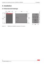
Installation and operating instructions, OMD200 and OMD300 4. Installation 4.1 Dimensional drawings 96
Open the catalog to page 12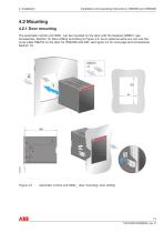
Installation and operating instructions, OMD200 and OMD300 4.2 Mounting 4.2.1 Door mounting The automatic control unit OMD_ can be mounted on the door with the fastener OMZD1, see Accessories, Section 10. Door drilling according to Figure 4.2. As an optional extra you can use the cover plate OMZC2 on the door for OMD200 and 300, see Figure 4.3 on next page and Accessories, Section 10. Automatic control unit OMD_, door mounting, door drilling
Open the catalog to page 13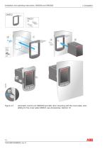
Installation and operating instructions, OMD200 and OMD300 Automatic control unit OMD200 and 300, door mounting with the cover plate, door drilling for the cover plate OMZC2, see Accessories, Section 10
Open the catalog to page 14
Installation and operating instructions, OMD200 and OMD300 4.2.3 DIN-rail mounting The automatic control unit OMD_ can be mounted on the 35 mm DIN-rail, see the Figure 4.4. Door drilling, if needed, according to Figure 4.4. As an optional extra you can use the cover plate OMZC2 on the door for OMD200 and OMD300, see Figure 4.5 and Accessories, Section 10. Automatic control unit OMD_, DIN-rail mounting, door drilling 15 1SCC390125M0203, rev. C
Open the catalog to page 15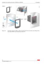
Installation and operating instructions, OMD200 and OMD300 Automatic control unit OMD_, DIN-rail mounting with the cover plate, door drilling for the cover plate OMZC2, see Accessories, Section 10
Open the catalog to page 16
5. Connecting Installation and operating instructions, OMD200 and OMD300 Only an authorised electrician may perform the electrical installation and maintenance of automatic transfer switches. Do not attempt any installation or maintenance actions when an automatic transfer switch is connected to the electrical mains. Before starting work, make sure that the switch is de-energised. 5.1 Power circuit Operating voltage: Main voltage: 208Vac - 480Vac (±20%) Phase setting with DIP switches: Single phase or Three-phase (default). OMD200: If the automatic control unit OMD200 is used without neutral...
Open the catalog to page 17All ABB Smart Power catalogs and technical brochures
 ABB AbilityTM Smart Sensor
12 Pages
 Bus couplers
3 Pages
 SlimLine XR
52 Pages
 SACE Emax 2
277 Pages
 Rotary cam switches OC10...25
80 Pages
 TruOne
68 Pages
 Switch-disconnectors
192 Pages
 OFAM/ OFAA
2 Pages
 SACE Tmax XT
8 Pages
 YO-YC Test unit
5 Pages
 Case study. PRAMAC
4 Pages
 Installation contactors
32 Pages
 Softstarter PSR, PSE and PSTX
68 Pages
 SNK Series Terminal Blocks
8 Pages
 Blackburn Storm Safe
4 Pages
 Twist Tail Brochure
2 Pages
 PMA - Automation Products
24 Pages
 Superstrut SilverGalv
2 Pages
 ABB Elkay EasyDALI brochure
20 Pages
 Pacific Intertie
2 Pages
 ABB Division
17 Pages
 ABB HVDC Classic
24 Pages
 Switches for PV application
108 Pages
 V400
V4002 Pages
 V16
V162 Pages
 P42E
P42E2 Pages
 Nightstar
2 Pages
 ROYCE THOMPSON
4 Pages
 Guideway & Serenga 2
28 Pages
 Analog signal converters
28 Pages


Archived catalogs
 EasyLine XLP
31 Pages
 Tmax UL/CSA Technical Catalog
288 Pages
 Switch fuses OS and OSM
116 Pages
 OC Cam Switches 10 to 25 Amperes
80 Pages
 SNK terminal blocks global catalog
236 Pages


- Connector
- ABB fitting
- Hydraulic fitting
- Screw-in fitting
- Data connector
- Metal fitting
- Quick coupling
- Metal connector
- Nickel-plated brass fitting
- Elbow fitting
- Polymer connector
- Screw-in connector
- Industrial connector
- ABB cable sleeve
- Plastic fitting
- ABB protection sleeve
- ABB cable gland
- Female fitting
- ABB waterproof cable gland
- Push-in fitting